Issue: 1.2-17-2 Ovation Systems Ltd Page 4
www.ovation.co.uk
2 Installation
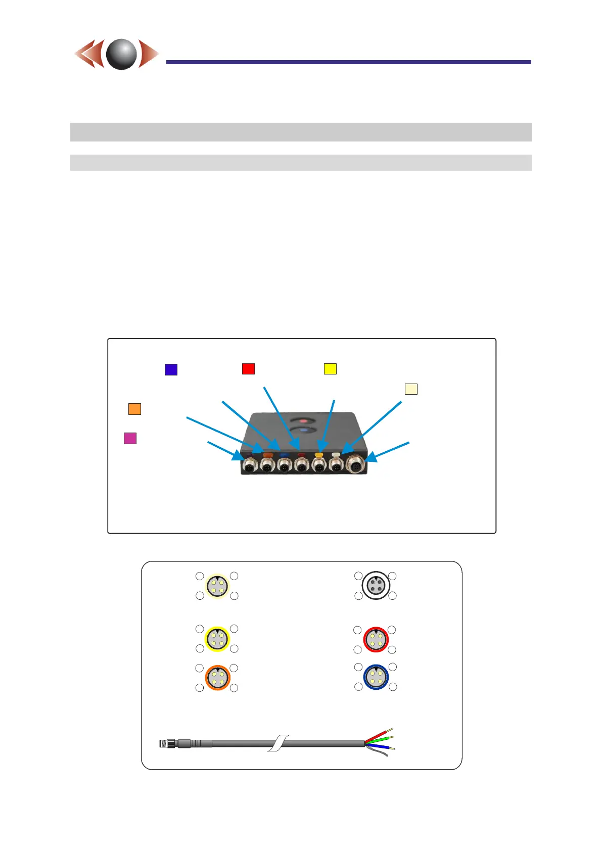
2.1 i-Conex Inputs & Outputs
FlashBack-4 is compatible with Ovation’s i-Conex interconnection system. i-Conex includes a
selection of cable assemblies that interface to commonly used power, video and audio
connectors (see Figure 4), as well as open leads for more complex installations. The
connections to the rear of FlashBack-4 are colour coded to indicate their function, as shown
in Figure 2, below. The cream i-Conex HD input auto-detects either Ovation’s digital HD
input format or two SD analogue inputs (camera inputs 2 & 4) as well as providing camera
power.
CAUTION► Only connect cables with the same colour code to each input.
TIP► Any cable may be lengthened by the in-line extension cables provided.
Figure 2: FlashBack-4C Single Rear Panel Connectors
Figure 3: i-Conex Connector Pin-outs
DC Power
6 to 32 V DC
(+ 2 external
trigger inputs)
i-Conex HD
Digital HD input
or SD 2 & 4 In
+ camera power
SD 1 & 3
Video In
+ camera power
2 x Audio In
+ mic bias
RS232
+ GPS power
(fixed to GPS)
Ethernet
i-Conex USB
Expansion Port
NB: Functions shown in are not yet operational grey
Camera Power
Camera Power
Mic Bias
(~3V DC)
Video Ground
Video Ground
Ground
Audio Ground
1
1
1
1
4
4 4
4
SD Video In 1
SD Video In 2
Or HD data
Audio In L
SD Video In 3
SD Video In 4
Or HD data
Audio In R
2
2
2
2
3
3 3
3
Rec Control 2
(record trigger)
6 to 28 V DC In
GPS Power
(3.3/5V DC)
Ground
1
1
4
4
TXD
RXD
2
2
3
3
Video Out
Ground
Audio Out L
Audio Out R
As looking into the i-Conex connectors
on the rear of a unit (not cable ends)
i-Conex cable colours
Pin 1 Red
Pin 2 Green
Pin 3 Blue
Pin 4 Screen
(input auto-detects between SD and HD camers)
Rec Control 1
(record switch)