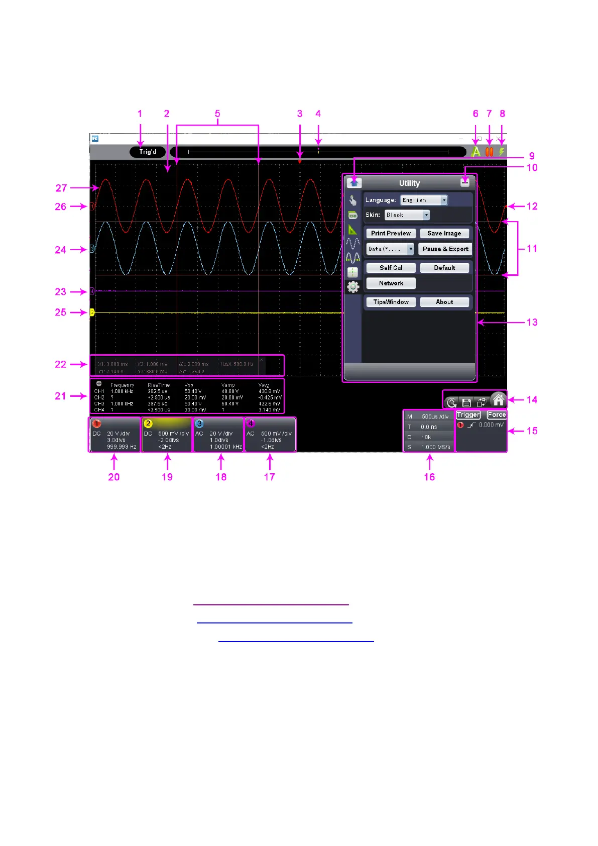
VI. Operation Interface of PC Software
Status Indicating Area: please refer to “Status Details List”
Red Pointer: to indicate the horizontal position of one conditioned trigger
Violet Pointer: to indicate the trigger position in the recorded data
Time Range measured by certain cursor measurement
Auto Set: please refer to xii. how to use main action button
Run/Stop: please refer to xii. how to use main action button
Single Trigger: please refer to xii. how to use main action button
Back to Home of Function Menu
Voltage Range measured by certain cursor measurement
Red Pointer: the trigger level position of Channel 1;
Yellow Pointer: the trigger level position of Channel 2;
Blue Pointer: the trigger level position of Channel 3;
Purple Pointer: the trigger level position of Channel 4
 Loading...