Via dragging Red / Yellow / Blue / Purple Pointer upwards or downwards, to adjust the trigger level position of Channel
1 / 2 / 3 / 4.
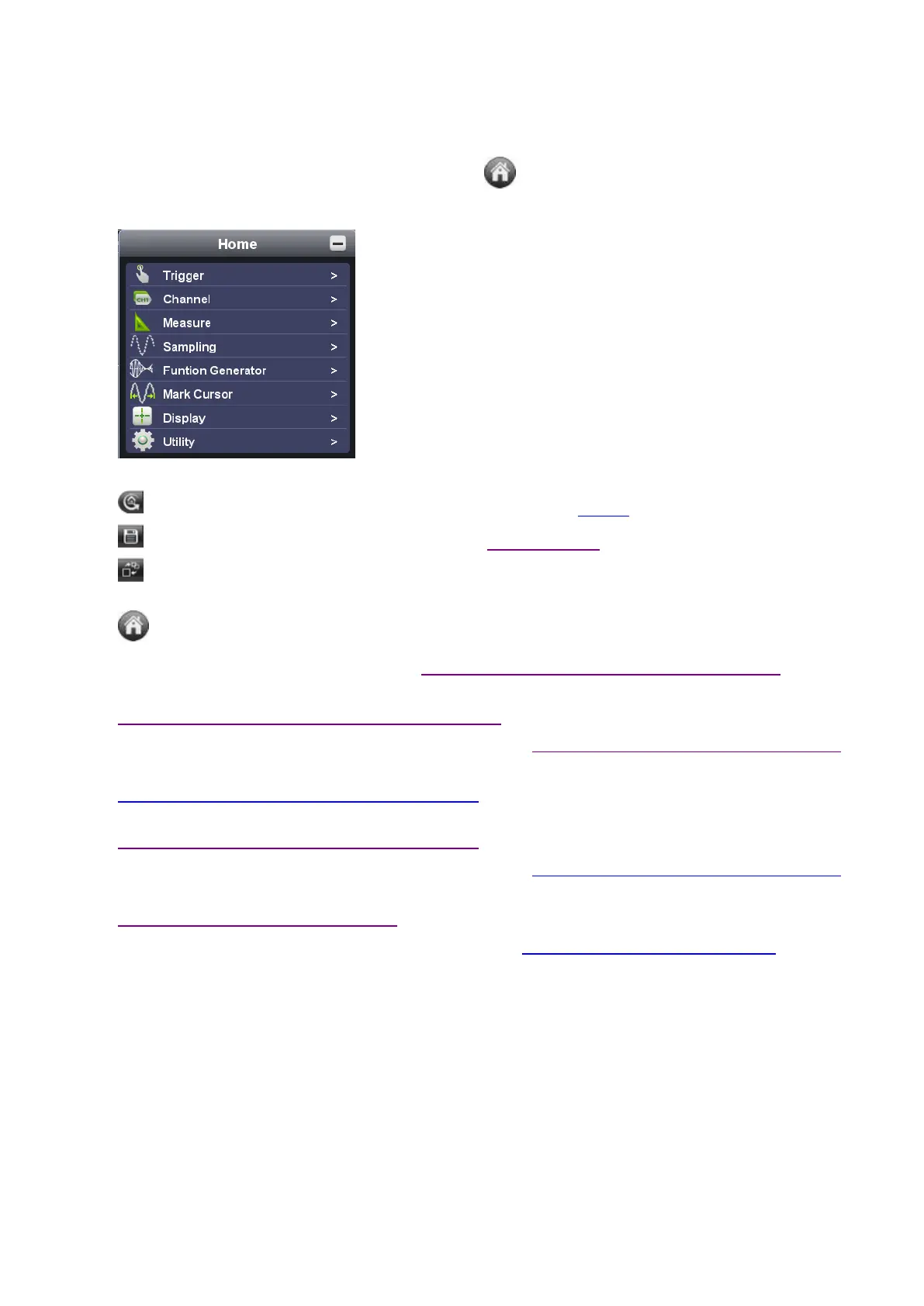
Function Menu: to hide/show it via mouse-clicking ; each side-bar icon matches
corresponding function, please refer to Home of Function Menu for details -
Shortcut to back to default factory settings, please refer to "Default" ;
Shortcut to export signal data, please refer to "Pause & Export" ;
Shortcut to switch between 3-window / 1-window VIEW. When working in 3-window VIEW, the
upper-left window is for XY mode.
Shortcut to hide/show Function Menu
Trigger extension window, please refer to iv. how to set the trigger system from PC software
Sample and Period extension window, please refer to
iii. how to set the horizontal system from PC software
Channel extension window for Channel 4, please refer to ii. how to set the vertical system from PC software
Channel extension window for Channel 3, please refer to
ii. how to set the vertical system from PC software
Channel extension window for Channel 2, please refer to
ii. how to set the vertical system from PC software
Channel extension window for Channel 1, please refer to ii. how to set the vertical system from PC software
Measurement Details extension window for Channel 1 / 2 / 3 / 4, please refer to
vi. how to use automatic measurement
Cursor Measurement extension window, please refer to ix. how to use cursor measurement
Purple Pointer: to show the grounding base point (zero point) of Channel 4; provided no Yellow
Pointer comes, it means Channel 4 is off.
Blue Pointer: to show the grounding base point (zero point) of Channel 3; provided no Red Pointer
comes, it means Channel 3 is off.
Yellow Pointer: to show the grounding base point (zero point) of Channel 2; provided no Yellow
Pointer comes, it means Channel 2 is off.
Red Pointer: to show the grounding base point (zero point) of Channel 1; provided no Red Pointer
comes, it means Channel 1 is off.
The Displayed Area of Input Signal from Channel 1.
 Loading...