4. Junior User Guidebook
Introduction to the Structure of the Oscilloscope
When you get a new-type oscilloscope, you should get acquainted with its front panel at
first and the SDS5032E(V) digital storage oscilloscope is no exception. This chapter
makes a simple description of the operation and function of the front panel of the
SDS5032E(V) oscilloscope, enabling you to be familiar with the use of the SDS5032E(V)
oscilloscope in the shortest time.
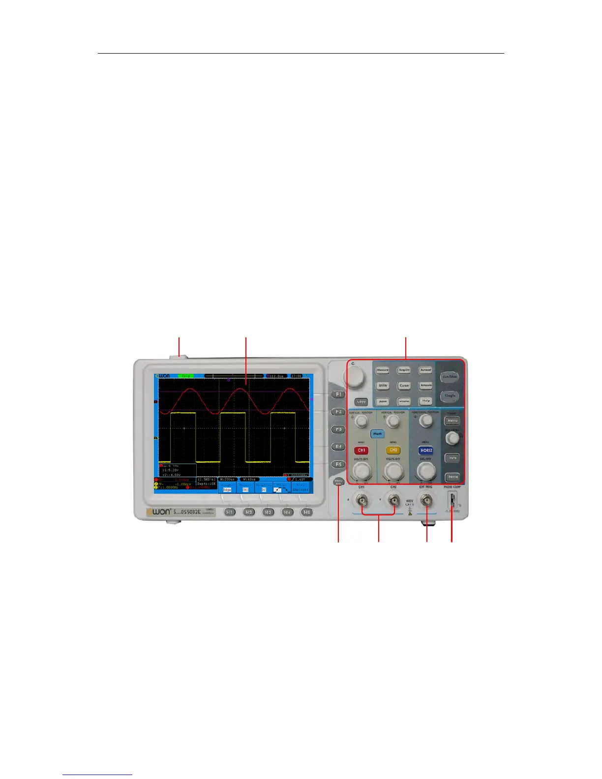
Front Panel
The SDS5032E(V) oscilloscope offers a simple front panel with distinct functions to users
for their completing some basic operations, in which the knobs and function pushbuttons
are included. The knobs have the functions similar to other oscilloscopes. The 5 buttons
(F1 ~ F5) in the column on the right side of the display screen or in the row under the
display screen (H1 ~ H5) are menu selection buttons, through which, you can set the
different options for the current menu. The other pushbuttons are function buttons,
through which, you can enter different function menus or obtain a specific function
application directly.
1 2 3
5
6
4
7
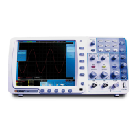
Fig. 4-1 Front panel
1. Power on/off
2. Display area
3. Control (key and knob) area
4. Probe Compensation: Measurement signal(5V/1KHz) output
5. EXT Trigger Input
6. Signal Input Channel
7. Menu off
6