2. Safety Terms and Symbols
Warning:
The channels should adopt common basis during measuring. To prevent short
circuits, the 2 probe ground must not be connected to 2 different non-isolated DC
level.
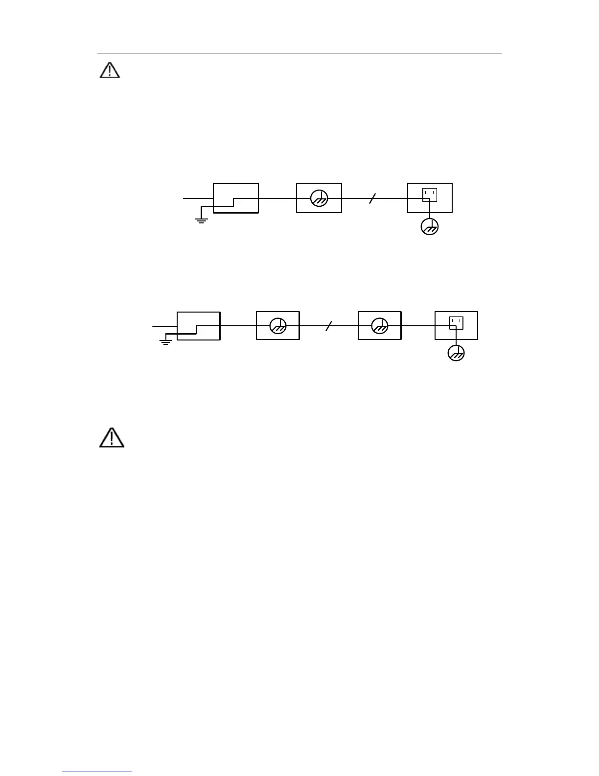
The diagram of the oscilloscope ground wire connection:
Ground Clip
Signal Input
Oscilloscope
Electrical OutletProbe
Power Cord
The diagram of the ground wire connection when the battery-powered oscilloscope is
connected to the AC-powered PC through the ports:
Ground Clip
Signal Input
Oscilloscope
(Battery-power)
PC Electrical OutletProbe
USB/VGA/COM/
LAN Cable
It is not allowed to measure AC power when the oscilloscope is AC powered, or when
the battery-powered oscilloscope is connected to the AC-powered PC through the
ports.
Warning:
To avoid fire or electrical shock, when the oscilloscope input signal
connected is more than 42V peak (30Vrms) or on circuits of more than
4800VA, please take note of below items:
z Only use accessory insulated voltage probes and test lead.
z Check the accessories such as probe before use and replace it if
there are any damages.
z Remove probes, test leads and other accessories immediately after
use.
z Remove USB cable which connects oscilloscope and computer.
z Do not apply input voltages above the rating of the instrument
because the probe tip voltage will directly transmit to the
oscilloscope. Use with caution when the probe is set as 1:1.
z Do not use exposed metal BNC or banana plug connectors.
z Do not insert metal objects into connectors.
3