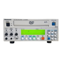
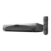
IN CAR MIC
CAMERA 1
CONTROL PANEL
GPIO/SERIAL
USB
GPS-ANT.
(OPTION)
CAMERA 2
AUDIO IN
VIDEO OUT
AUDIO OUT
12
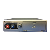
Control Reference Guide
(continued)
Rear panel (1)
IN CAR MIC connector
(Pin jack)
This is a mic level signal input.
AUDIO IN 1, 2 connectors
(Pin jack)
These are line level signal inputs.
The output signals of audio
components can be connected here.
AUDIO OUT connector
(Pin jack)
This is a line level signal output.
Accepts connection of the cable
attached to the separately sold
Remote Control Panel.
CAMERA2 connector
(Pin jack)
This is a composite signal input.
Connect a commercially available
camera.
VIDEO OUT connector
(Pin jack)
This is a composite signal output.
Provides output of the video applied
to the [CAMERA1] or [CAMERA2]
connector.
Accepts connection of the cable
attached to the separately sold
Remote Control Panel.
CONTROL PANEL connector
Connect the separately sold Remote
Control Panel using the cable attached
to the Remote Control Panel.
CAMERA1 connector
Connect the separately sold Color
Camera using the cable attached to
the Camera.
 Loading...