1
1-370
HOW TO INSTALL THE INDOOR UNIT
Low Silhouette Ducted Type (Type F1)
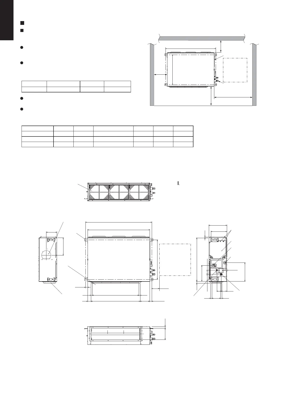
4-1. Required Minimum Space for Installation and Service
This air conditioner is usually installed above the ceiling so
that the indoor unit and ducts are not visible. Only the air
intake and air outlet ports are visible from the unit bottom.
The minimum space for installation and service is shown in
Fig. 1-90 and Table 1-7.
Type 36, 45, 50 60, 71 100, 125, 140
A (Length) 867 1,067 1,467
It is recommended that space be provided (450 × 450 mm)
for checking and servicing the electrical system.
The detailed dimensions of the indoor unit is shown in Fig.
1-91 and Table 1-8.
636
33.4
33.4
B
D C D
154
(150)
54
700
30
290
255
15
14023 23
113 65
70 90
26.1
300
186 27
256
172
280
g
h
f
i
c
d
b
a
e
j
Fig. 1-90
Table 1-7
Unit: mm
Type A B C D E F
36, 45, 50 867 800 450 (Pitch 150 × 3) 71 592 12
60, 71 1,067 1,000 750 (Pitch 150 × 5) 21 792 16
100, 125, 140 1,467 1,400 1,050 (Pitch 150 × 7) 71 1,192 20
Table 1-8
Unit: mm
Air intake port side
Air outlet duct side
F-ø3 holes
E (Flange O.D.)
A (Suspension bolt pitch)
Unit: mm
Fig. 1-91
a) Refrigerant tubing joint (liquid tube)
b) Refrigerant tubing joint (gas tube)
c) Upper drain port VP25 (O.D. 32 mm)
200 flexible hose supplied
d) Bottom drain port VP25 (O.D. 32 mm)
e) Suspension lug (4 – 12 × 30 mm)
f ) Power supply outlet
g) Fresh air intake port (ø150 mm)
h) Flange for flexible air outlet duct
i ) Electrical component box
j ) Filter
Inspection
access
450 × 450
(Field supply)
A (Suspension bolt pitch)
Min.250
Electrical
component box
Inspection
access
450 × 450
Refrigerant
tubing
Min.650
Indoor unit
Min.400
min.250
Unit: mm
636
SM830231-02Single欧州.indb370SM830231-02Single欧州.indb370 2014/09/1913:22:002014/09/1913:22:00
 Loading...