1
1-401
1-12. How to select AHU system
System lineup
AHU system selection guideline
* Mix connection with standard indoor units is not allowed.
* The system is applicable to the above models.
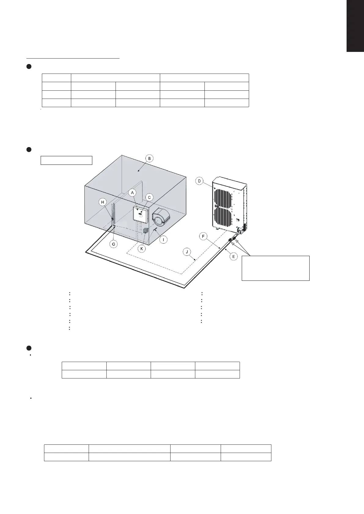
System Overview
Piping design regulation
Connecting pipe dimension to heat exchanger of AHU
Capacity
U-100PE1E8A
CZ-280PAH1
U-125PE1E8A CZ-280PAH1
10 kW
12.5 kW
14 kW U-140PE1E8A U-140PE1E5A
U-125PE1E5A
U-100PE1E5A
CZ-280PAH1 CZ-280PAH1
CZ-280PAH1
CZ-280PAH1
Outdoor combination Connectable AHU-kit combination
Capacity Model name Liquid pipe Gas pipe
A
AHU kit controller box (with control PCB)
B
AHU equipment (Field supplied)
C
AHU kit controller (Option parts)
D
Outdoor unit
E
Gas piping (Field supplied)
F
Liquid piping (Field supplied)
G
Thermistor for Liquid pipe (E1)
H Thermistor for Heat exchanger pipe middle (E2)
I
Thermistor for Suction air (TA)
J
Inter-unit wiring
K
Magnetic relay for operating the blower (Field supplied)
Strainer (Liquid pipe &
Gas pipe) Min. ø25.4,
#100 (Field supply)
Single connection
* Single connection type only
System piping length (Charging with refrigerant)
At the time of shipment from the factory, the outdoor unit is charged with enough refrigerant for an equivalent
pipe length of 30m.
If the equivalent piping length used is 30m or less, no additional charge will be necessary.
If the equivalent piping length is between 30 and 50m, charge with additional refrigerant according to the
equivalent length given in the following table.
10-14kW
ø9.52mm
CZ-280PAH1
ø15.88mm
Capacity Additional charge amount Equivalent length Minimum length
10-14kW 50m
50g/m
5m
SM830231-02Single欧州.indb401SM830231-02Single欧州.indb401 2014/09/1913:22:072014/09/1913:22:07
 Loading...