1
1-382
Fig. 1-108
Table 1-11
Fig. 1-109
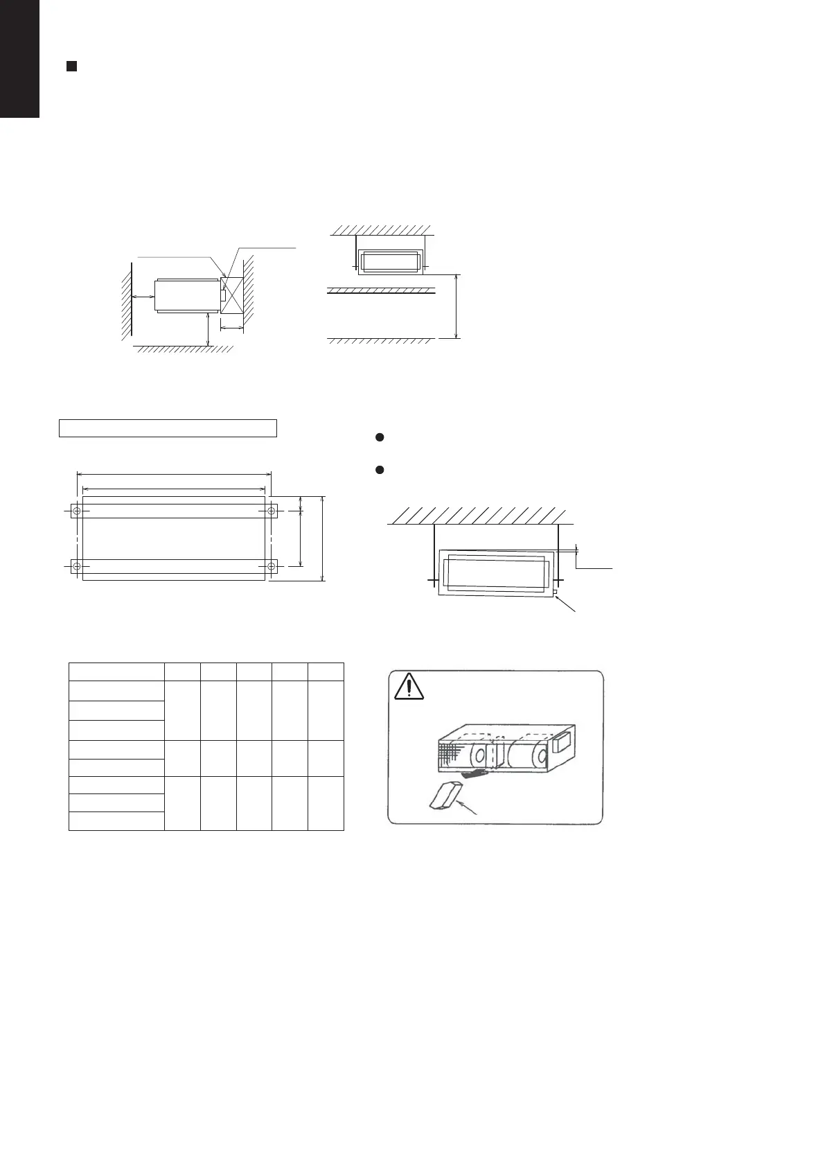
SELECTING THE LOCATION FOR THE INDOOR UNIT
5-1. Required Minimum Space for Installation and Service
Provide a check port on the piping side ceiling for repair and maintenance.
Install the indoor unit once the following conditions are satisfied and after receiving the customer approval.
1.
2.
The indoor unit must be within a maintenance space.
The indoor unit must be free from any obstacles in path of the air inlet and outlet, and must allow spreading of air
throughout the room.
POSITION OF SUSPENSION BOLT
1 ~ 3mm
Drainage hole
Unit: mm
Remove the absorber at air
return hole before installation.
Absorber
ATYPE B C D E
S-36PN1E5A
S-45PN1E5A
S-50PN1E5A
S-60PN1E5A
S-71PN1E5A
S-100PN1E5A
S-125PN1E5A
S-140PN1E5A
840 780 523 64 650
1060 1000 523 64 650
1260 1200 523 64 650
(Uint : mm)
Inspection hole
<Front>
Control box
Top view Front view
(600 x 600)
600
600
1000
Above 250cm
A
B
C D
E
Apply a joint-canvas between the unit and duct to
absorb unnecessary vibration.
Install the unit leaning to a drainage hole side as a
figure for easy water drainage.
If the height from the floor to ceiling exceeds three meters, air flow distribution deteriorates and the effect is decreased.
CAUTION
SM830231-02Single欧州.indb382SM830231-02Single欧州.indb382 2014/09/1913:22:032014/09/1913:22:03
 Loading...