9.8. VCR MECHANISM UNIT
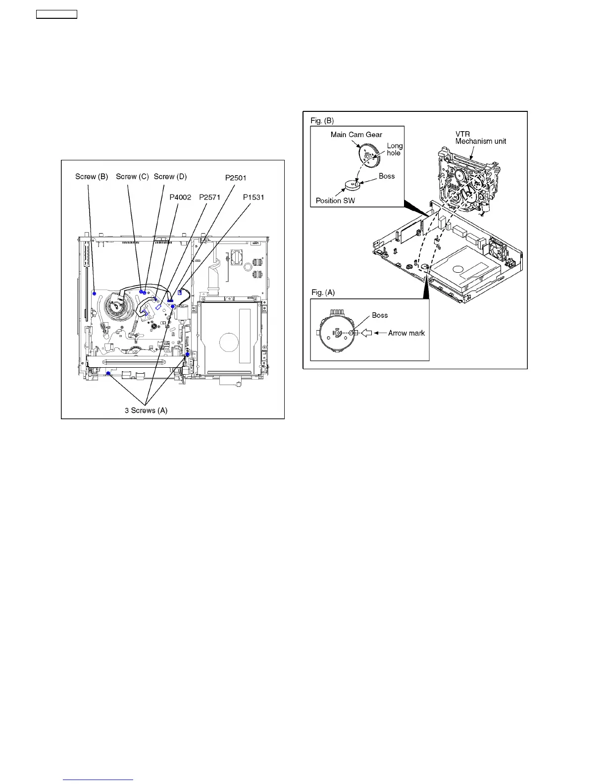
1. Disconnect 3 Connectors (P1531, P2501 and P4002).
2. Remove 3 black Screws (A), Screw (B), Screw (C)
and Screw D).
3. Lift up VCR Mechanism Unit perpendicularly so to
disconnect Connectors (P2571 and P3001).
Note:
When you lift up VCR Mechanism Unit, because
connections of P2501 and P3001 are tight,
pay attention to that.
9.8.1. CAUTION FOR ATTACHING VCR
MECHANISM UNIT
1. Because Position SW should be set to "Eject Position",
refer to fig.(A) and set the position switch so that the boss
and arrow mark come on a straight line.
2. Attach VCR Mechanism Unit so that Boss of Position SW is
put into long hole of Main Cam Gear, refer to Fig. (B).
30
DMR-EZ45VEB
 Loading...