MEWNET-W Mode
FP2 Multi-wire Link Unit
4-5
4.2 PC Link
Link area configuration
For PC link 0
For PC link 1
(words)
L: 1,024 points
L: 1,024 points
Link relays (L)
For PC link 0
For PC link 1
(words)
LD: 128 words
LD: 128 words
Link registers (LD)
D
Link areas consist of link relays and link registers, and are divided into areas for
PC link 0 and PC link 1 and used with those units.
D
The link relay which can be used in an area for either PC link 0 or PC link 1 is
maximum 1,024 points (64 words), and the link register is maximum 128 words.
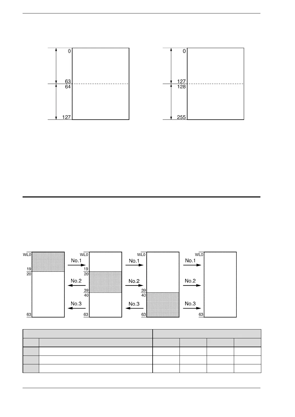
4.2.3 Link Area Allocation Example
The areas for PC link 0 and PC link 1 are divided into send areas and receive areas.
The link relays and link registers are sent from the send area to the receive area of a
different programmable controller. Link relays and link registers with the same numbers
as those on the transmission side must exist in the receive area on the receiving side.
Example of link area allocation
Link relay
allocation
Send area
Send area
Receive
area
Send area
Receive
area
Receive
area
Receive
area
Receive
area
Unit No.1 Unit No.2 Unit No.3 Unit No.4
System register Settings for the various units
No. Setting contents for PC link 0 No.1 No.2 No.3 No.4
40 Link relay range 64 64 64 64
42 Starting no. for link relay transmission 0 20 40 0
43 Link relay transmission size 20 20 24 0