General SpecificationsFP2 Multi-wire Link Unit
1-17
1.4 Confirming the Design Contents
1.4.3 Confirmation When Multiple Units are Installed
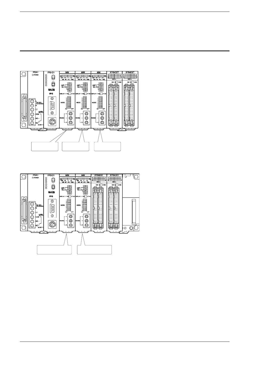
Multi-wire link units which have been installed are called root No. 1, root No. 2, root No.
3, and root No. 4, in sequential order, with root No. 1 being closest to the CPU.
Root No.2 Root No.3Root No.1
When using PC link communicationinthe W mode, these are labeled “For PC link 0” and
“For PC link 1”, in order of their proximity to the CPU.
for PC link 0
for PC link 1
When using PC link communication in the W2 mode, the link relays and link registers
haveseparate workareas forPC link0 andPC link1, and settingsmustbe enteredsepa-
rately for each unit.