Chapter 1 Preparation — About your projector
ENGLISH - 27
15 <AC IN> terminal
Connect the supplied power cord.
16 Burglar hook port
Attaches a burglar prevention cable, etc.
Attention
f Do not block the ventilation ports (intake and exhaust) of the projector.
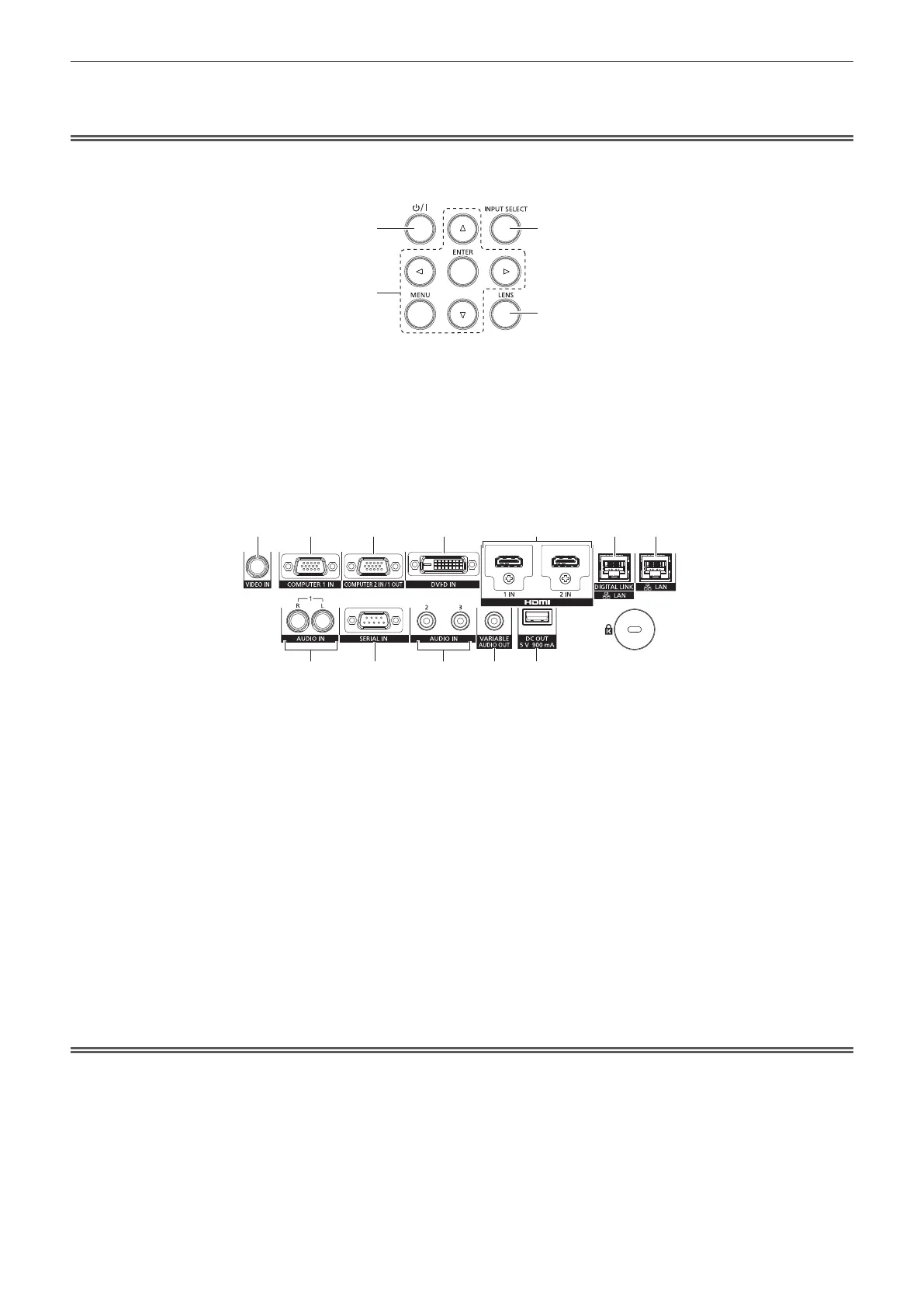
r Control panel
3
4
1
2
1 Power <v/b> button
Sets the projector to the state where the projector is turned
off (standby mode) when the <MAIN POWER> switch on the
projector is set to <ON> and in projection mode.
Sets the projector to projection mode when the power is
switched off (standby mode).
2 <MENU> button/<ENTER> button/asqw buttons
Used to navigate through the menu screen.
Also used to enter a password in the [SECURITY] menu or
enter characters.
3 <INPUT SELECT> button
Switches the input signal to project. (x page 50)
4 <LENS> button
Adjusts the focus and shift (position) of the lens.
r Connecting terminals
8 9 10 11 12
1 2 3 4 5 6 7
1 <VIDEO IN> terminal
This is a terminal to input video signal.
2 <COMPUTER 1 IN> terminal
This is a terminal to input the RGB signal, YC
B
C
R
/YP
B
P
R
signal,
or Y/C signal.
3 <COMPUTER 2 IN/1 OUT> terminal
This is a terminal to input the RGB signal or YC
B
C
R
/YP
B
P
R
signal.
Also, the RGB signal or YC
B
C
R
/YP
B
P
R
signal input to the
<COMPUTER 1 IN> terminal can be output to an external
device. Video signal is output when the input is switched to
COMPUTER1.
4 <DVI-D IN> terminal
This is a terminal to input the DVI-D signal.
5 <HDMI 1 IN> terminal/<HDMI 2 IN> terminal
This is a terminal to input the HDMI signal.
6 <DIGITAL LINK/LAN> terminal
This is a terminal to connect a device that transmits video
signal or audio signal via the LAN terminal. Also, this is the LAN
terminal to connect to the network.
7 <LAN> terminal
This is the LAN terminal to connect to the network.
8 <AUDIO IN 1> terminal
This is a terminal to input audio signal. There are right input
<R> and left input <L>.
9 <SERIAL IN> terminal
This is the RS-232C compatible terminal to externally control
the projector by connecting a computer.
10 <AUDIO IN 2> terminal/<AUDIO IN 3> terminal
This is a terminal to input audio.
11 <VARIABLE AUDIO OUT> terminal
This is a terminal to output the audio signal input to the
projector.
12 <DC OUT> terminal
This is the USB terminal dedicated for power supply. (DC5 V,
maximum 900 mA)
This can be used when a power is needed to be supplied to a
wireless display adaptor, etc.
Attention
f When a LAN cable is directly connected to the projector, the network connection must be made indoors.
 Loading...