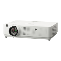
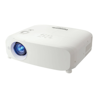
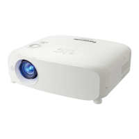
r Cautions when setting the projectors
f If you want to use the projector other than the way of setting on the desk/oor with the adjustable feet or mounting on the
ceiling, use the three screw holes for ceiling mounting (as shown below) to x the projector.
(Screw: M4; Depth of the screw hole: 8 mm (5/16"); Torque: M4 1.25 ± 0.2 N·m)
In addition, always keep a gap of more than 20 mm (25/32") between the bottom of the projector and installation surface.
Make sure that there is no clearance of at least 20 mm (25/32″) between the screw holes for ceiling mounting and the
installation surface by inserting supports (metallic) between them.
f Do not stack the projectors.
f Do not use the projector supporting it by the top.
f Do not block the ventilation ports (intake and exhaust) of the projector.
f Avoid heating and cooling air from the air conditioning system directly blow to the ventilation ports (intake and exhaust) of
the projector.
f Do not install the projector in a conned space.
When placing the projector in a conned space, a ventilation and/or air conditioning system is required. Exhaust heat may
accumulate when the ventilation is not enough, triggering the protection circuit of the projector.
Security
Take safety measures against following incidents.
f Personal information being leaked via this product.
f Unauthorized operation of this product by a malicious third party.
f Interfering or stopping of this product by a malicious third party.
Security instruction (x pages 85, 92, 110)
f Make your password as difcult to guess as possible.
f Change your password periodically.
f Panasonic or its afliate company never inquires a password directly to a customer. Do not tell your password in case you
receive such an inquiry.
f The connecting network must be secured by rewall or others.
f Set a password for web control and restrict the users who can log in
.
The positions of adjustable feet and the
screw holes for ceiling mounting
Adjustable feet
Over 20 mm
(25/32″)
Installation surface
Screw holes for
ceiling mounting
f
Make sure the air ow into the air intake
port (bottom), failure to do so may cause the
projector cannot work.
Air intake port
(bottom)
500 mm (19-11/16")
or longer
1 000 mm
(39-3/8") or longer
7 mm (9/32")
or longer
500 mm (19-11/16")
or longer
200 mm (7-7/8")
or longer
ENGLISH - 19
Chapter 1 Preparation - Precautions for use
 Loading...


