2-5
Design of VRF SYSTEM
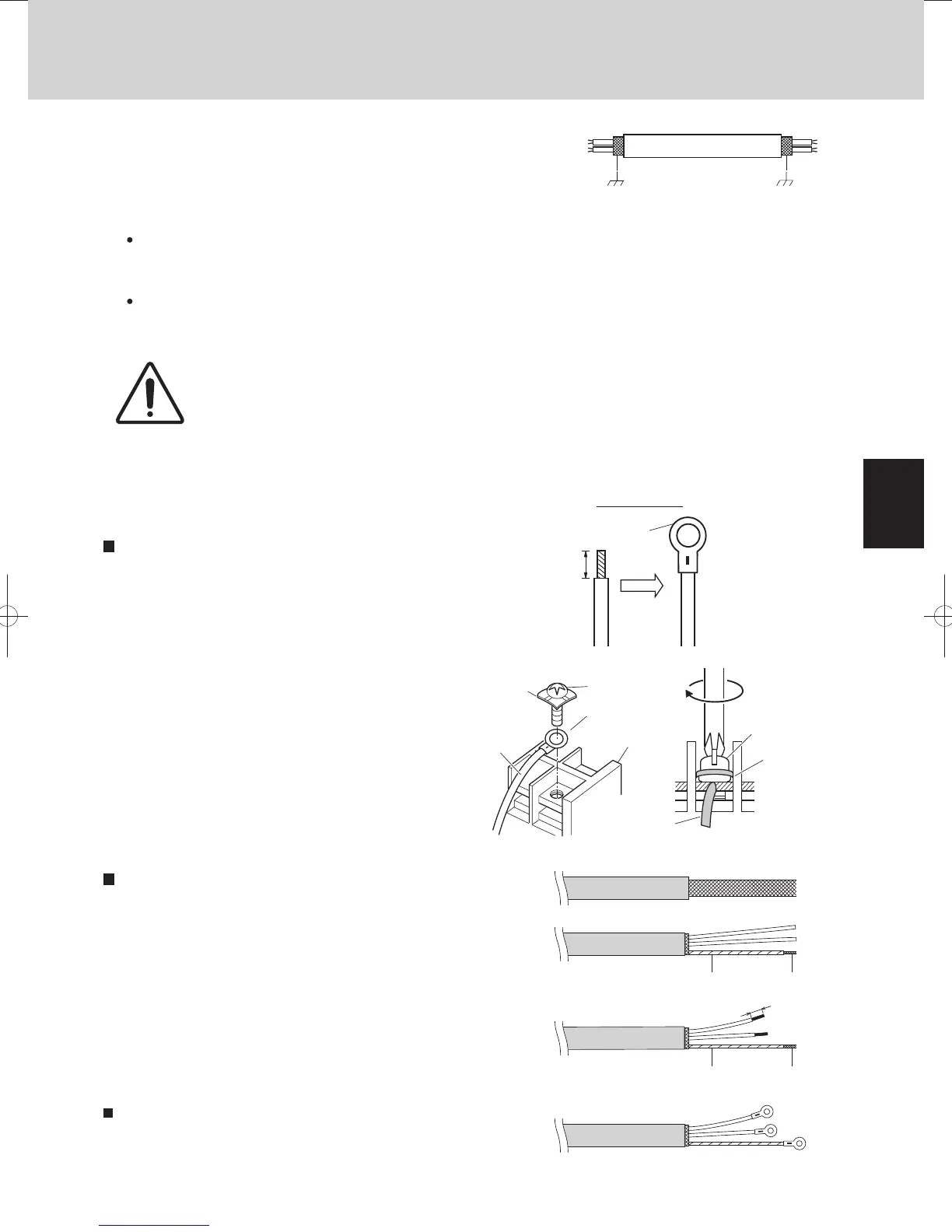
1. Electrical Wiring
Shielded wire
Ground Ground
Screw and
Special washer
Ring
pressure
terminal
Terminal board
Ring pressure
terminal
Screw
Special
washer
Wire
Wire
Insulation tape
8mm
Insulation tape
Shield mesh
Shield mesh
Fig. 2-5
Stranded wire
Ring
pressure
terminal
Strip 10 mm
Fig. 2-6
Fig. 2-7
Fig. 2-8
Fig. 2-9
Fig. 2-10
Fig. 2-11
(5)
Use shielded wires for inter-unit control wiring (c) and
ground the shield on both sides, otherwise misoperation
from noise may occur. (Fig. 2-5)
Connect wiring as shown in Section “1-3. Wiring System
Diagrams”.
(6) Connecting cable between indoor unit and outdoor unit shall be approved polychloroprene sheathed
5 or 3 *1.5 mm
2
flexible cord. Type designation 60245 IEC 57 (H05RN-F, GP85PCP etc.) or heavier
cord.
WARNING
Loose wiring may cause the terminal to overheat or result in unit malfunction.
A fire hazard may also occur.
Therefore, ensure that all wiring is tightly connected.
When connecting each power wire to the terminal, follow the instructions on “How to connect wiring to the terminal”
and fasten the wire securely with the fixing screw of the terminal board.
How to connect wiring to the terminal
For stranded wiring
(1)
then strip the insulation to expose
the stranded wiring about 10 mm and
tightly twist the wire ends. (Fig. 2-6)
(2)
remove the terminal screw(s) on the
terminal board.
(3)
pliers, securely clamp each stripped
wire end with a ring pressure terminal.
(4)
Cut the wire end with cutting pliers,
Using a Phillips head screwdriver,
Using a ring connector fastener or
Place the ring pressure terminal,
and replace and tighten the removed
terminal screw using a screwdriver.
(Fig. 2-7)
Examples of shield wires
(1)
(2)
together.
Coat with insulation tube or wrap insulation tape after
putting tightly. (Fig. 2-9)
(3)
(4)
Remove cable coat not to scratch braided shield. (Fig. 2-8)
Ravel braided shield carefully and put tightly braided shield
Remove coat of signal wire. (Fig. 2-10)
Connect signal wire removed coat and shield wire with
pressure terminal. (Fig. 2-11)
Earth wire for power supply
The earth wire should be longer than the other lead wires for
electrical safety.
Use the standard power supply cables for Europe (such as H05RN-F or H07RN-F which conform to
CENELEC (HAR) rating specifications) or use the cables based on IEC standard. (60245 IEC57, 60245
IEC66)
TDxxxxxx-002WAYVRF.indb5TDxxxxxx-002WAYVRF.indb5 2014/01/3017:52:302014/01/3017:52:30
 Loading...


