4-17
VRF SYSTEMS Indoor Unit Specifi cations
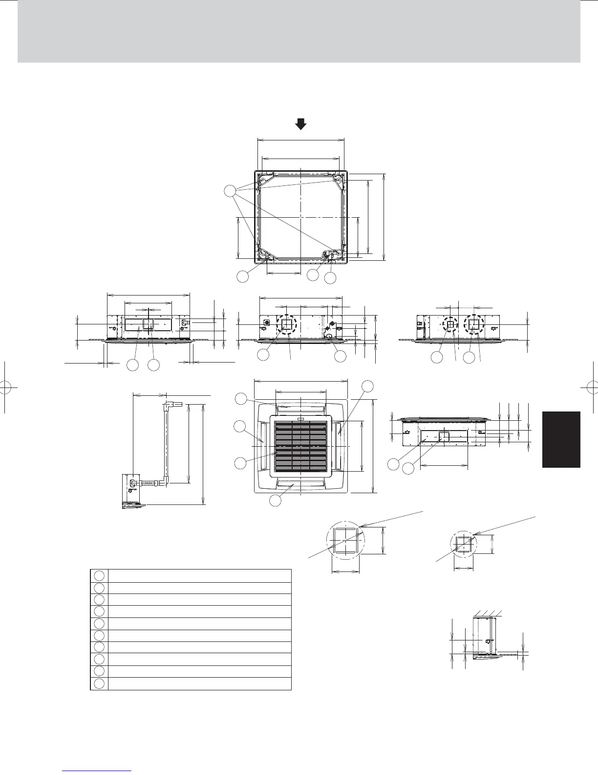
1. 4-Way Cassette Type (U1 Type)
1-3. Dimensional Data
30
18
82 160
480
View X
<Filter dimension>
Detailed view Y
Raise dimension of drain tube
Detailed view Z
860~910
(Ceiling opening dimensions)
860~910
(Ceiling opening dimensions)
786
(Suspension bolt pitch)
324
840
145
271
514
115
950
840
480
2
50
745
(Suspension bolt pitch)
118
160
167
130
124
130
95
421
160
Less than 35
Less than 35
Less than 300
Less than 670
Less than 850
180
12495
167
(411)
42
121
515
950
115
80
80
33.5 256
50
8
4
6
2
2
2
2
1
78
3
5
7
9
* The length of the suspension bolts
should be selected so that there is
a gap of 30 mm or more below the
lower surface of the ceiling (18 mm
or more below the lower surface of
the main unit), as shown in the
figure at right. If the suspension
bolt is too long, it will contact
the ceiling panel and the unit
cannot be installed.
Air intake
Discharge outlet
Refrigerant tubing (liquid tube)
ø6.35 (flared)
Refrigerant tubing (gas tube)
ø12.7 (flared)
Drain tube connection port VP25 (outer dia.
ø32)
Power supply port
Discharge duct connection port (
ø150)
Vaporizing-type humidifier (optional) installation area
Suspension bolt hole (4-12
× 30 elongated hole)
Fresh air intake duct connection port (
ø100) *
* Necessary to provide optional air intake kit.
ø162
ø113
4 - ø3 burring hole
4 - ø3 burring hole
1
2
3
4
5
6
7
8
9
10
Indoor unit : S-22MU1E5A/28MU1E5A/36MU1E5A/45MU1E5A/56MU1E5A
X
Y Z Y
unit: mm
520 x 520 x 16
7
10
7
TD831172-00VRFSYSINDOOR.indb17TD831172-00VRFSYSINDOOR.indb17 2014/04/2416:49:122014/04/2416:49:12
 Loading...


