iv
Section 1: OUTLINE OF VRF SYSTEMS ................................................................................ 1-1
*Refer to the Technical Data of Outdoor Unit.
Section 2: DESIGN OF VRF SYSTEMS ................................................................................. 2-1
1. Electrical Wiring .................................................................................................. 2-2
2. SELECTING THE INSTALLATION SITE ............................................................. 2-9
3. How to install the indoor unit ............................................................................. 2-15
4. Optional Parts ................................................................................................... 2-50
Section 3: Control of VRF SYSTEMS .................................................................................... 3-1
*Refer to the Technical Data of Outdoor Unit.
Refer to the following contents in the high-spec wired remote controller (CZ-RTC3)
1. Operating Instructions ......................................................................................... 3-2
2. Installation Instructions ..................................................................................... 3-23
Section 4: VRF SYSTEMS INDOOR UNIT SPECIFICATIONS ............................................... 4-1
1. 4-Way Cassette Type (U1 Type) .......................................................................... 4-2
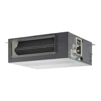
2. Low Silhouette Ducted Type (F2 Type) .............................................................. 4-25
3. 4-Way Cassette 60×60 Type (Y2 Type) ............................................................. 4-49
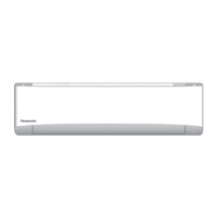
4. Wall Mounted Type (K2 Type) ............................................................................ 4-63
5. Wall Mounted Type (K1 Type) ............................................................................ 4-73
6. Ceiling Type (T2 Type) ....................................................................................... 4-85
7. Fresh Air Intake ................................................................................................. 4-98
Section 5: TEST RUN .............................................................................................................. 5-1
*Refer to the Technical Data of Outdoor Unit.
Refer to the following operations in the high-spec wired remote controller (CZ-RTC3)
1. Test Run ............................................................................................................. 5-2
2
. Auto Address Setting .......................................................................................... 5-3
Section 6: ELECTRICAL DATA .............................................................................................. 6-1
1. 4-Way Cassette ................................................................................................... 6-2
2. 4-Way Cassette 60×60 ....................................................................................... 6-3
3. Low Silhouette Ducted ........................................................................................ 6-4
4. Ceiling ................................................................................................................. 6-5
5. Wall Mounted ...................................................................................................... 6-6
Section 7: PCB AND FUNCTIONS ......................................................................................... 7-1
1. Outdoor Unit Control PCB
*Refer to the Technical Data of Outdoor Unit.
2. Indoor Unit Control PCB Switches and Functions .............................................. 7-2
Section 8: CAPACITY TABLE ................................................................................................. 8-1
For 2WAY VRF SYSTEM
1. Cooling Capacity of Indoor Unit .......................................................................... 8-2
For 3WAY VRF SYSTEM
2. Cooling Capacity of Indoor Unit ........................................................................ 8-45
For MINI VRF SYSTEM
3. Cool
ing Capacity of Indoor Unit ........................................................................ 8-88
Section 9: RENEWAL ............................................................................................................. 9-1
*Refer to the Technical Data of Outdoor Unit.
Contents
TD831172-00VRFSYSINDOOR.indb5TD831172-00VRFSYSINDOOR.indb5 2014/06/1910:37:592014/06/1910:37:59

 Loading...


