2-34
Design of VRF SYSTEM
3. How to install the indoor unit
(6)
There is a outside air intake duct connection port (cut out hole) at the left-rear of the indoor unit for drawing in fresh air.
If it is necessary to draw in fresh air, remove the cover by opening the hole and connecting the duct to the indoor unit through
the connection port. (Refer to Fig. 2-59)
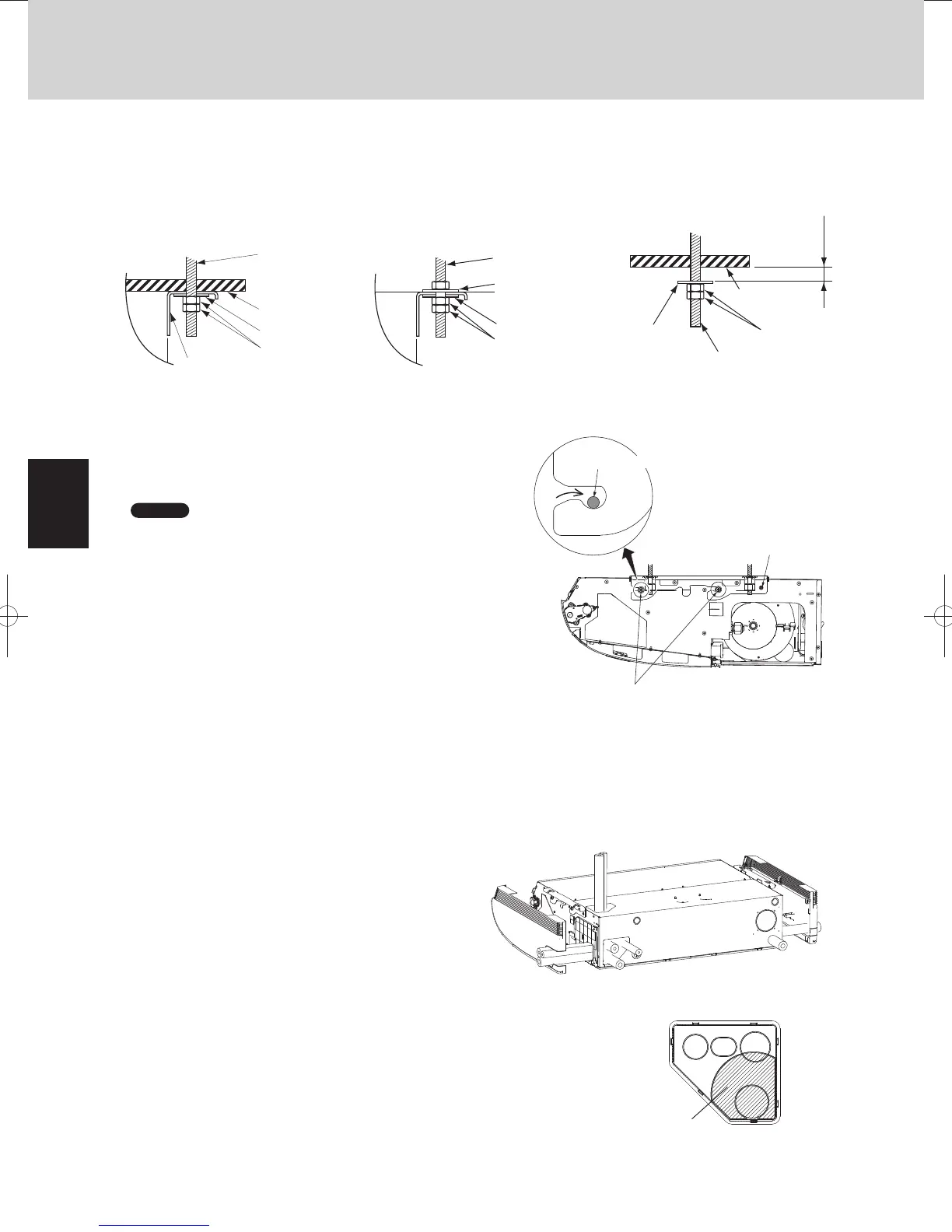
Carry out the preparation for suspending the indoor unit.
The suspension method varies depending on whether there is a suspended ceiling or not. (Figs. 2-70 and 2-71)
(7) Suspend the indoor unit as follows:
a) Install the bracket to the suspension bolt. Stick it onto the ceiling surface. (Fig. 2-70~2-72)
b)
*
Suspend the indoor unit to the bracket.
Tighten the M8 suspension bolts and fix the indoor unit in
place. (Fig. 2-73)
Bracket
Suspension bolt
(not supplied)
Ceiling surface
Unit
Washer (supplied)
Double nut
(not supplied)
Fig. 2-70
Suspension bolt
(not supplied)
Washer
(not supplied)
Unit
Washer (supplied)
Double nut
(not supplied)
Fig. 2-71
Suspension bolt
Double
(not supplied)
nut
Washer
(supplied)
Ceiling
surface
Approx.
25 mm
Fig. 2-72
M4 screw for preventing
bracket from taking off
M8 suspension bolts
M8 suspension bolt
Fig. 2-73
NOTE
The ceiling surface is not always level. Confirm that the indoor
unit is evenly suspended. For the installation to be correct,
leave a clearance of about 10 mm between the ceiling panel
and the ceiling surface and fill the gap with an appropriate
insulation or filler material.
3-4-4. Duct for Fresh Air (Field supply)
The positions of the refrigerant tubing connections are shown
at right. (The tubing can be routed in 3 directions.)
(Fig. 2-74)
When routing the tubing out through the top or right sides,
cut out the cover of the top panel and cut notches in the side
panel (Refer to fig. 2-59).
If the tubing is to be routed out together, use a box cutter or similar tool to cut out the part
of the cover indicated by the marked area (Fig. 2-75), to match the positions of the tubes.
Then draw out the tubing.
3-4-5. Shaping the Tubing
Fig. 2-74
Fig. 2-75
Cover
TDxxxxxx-002WAYVRF.indb34TDxxxxxx-002WAYVRF.indb34 2014/01/3017:52:312014/01/3017:52:31
 Loading...


