2-58
Design of VRF SYSTEM
4. Optional Parts
(2) Notes on Installation
(1) Wiring
Insulation
Fig. 2-162
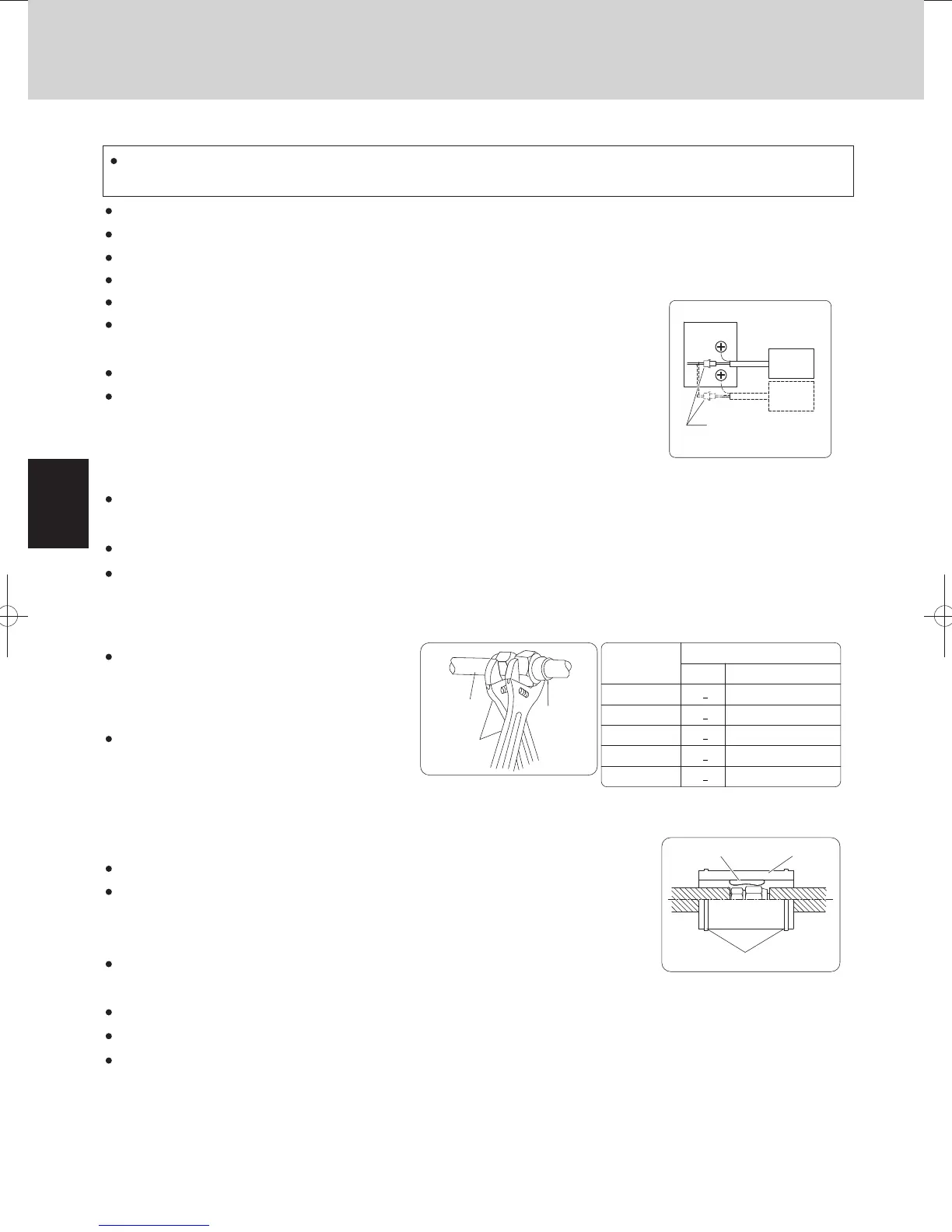
Tightening torque
Tubing size
ø6.35 (1/4")
ø9.52 (3/8")
ø15.88 (5/8")
ø19.05 (3/4")
Approx.
140 – 180
Approx.
340 – 420
Approx.
680 – 820
Approx.
1,000 – 1,200
Connecting
joint
Connecting
tube
Spanner
Table 2-7. Tightening Torque
Flare insulator
Insulating tape
Vinyl clamp
Approx.
490 – 610
N
•
m
{kgf
•
cm}
ø12.7 (1/2")
38
+
4
55
+
6
75
+
7
110
+
10
16
+
2
Be sure to provide insulation after finishing leak inspection.
For the direction for connecting the indoor and outdoor unit and RAP Valve Kit, be sure to follow the instructions
on the label of the valve body.
Be sure to secure the valve body by using its structure with the suspension bolt, etc.
Install the valve body within as shown in Fig. 2-160. a distance of 30 m from the indoor unit
Put the 6P connector from the RAP Valve Kit through the power inlet
and connect it to the 6P connector (yellow). (See Fig. 2-161)
(2) Refrigerant Tubing
(3) Insulation
Be sure to use 2 spanners together for removing
Secure the supplied cable with the binding band inside the unit.
the flare nut at the tubing connection or when
tightening the flare nut during tubing connection.
To prevent destruction in the flared portion due to
over-tightening the flare nut, tighten the nut using
the table at the right as a standard torque.
Be sure to provide insulation to the tubing.
Next, put the supplied flare insulator around the flare nut portion and secure both ends with the vinyl clamps.
Failure to provide insulation may cause water leakage due to condensation.
Thermal insulation is not supplied with the connecting tube (for connecting to the ø12.7 gas tube).
If this tube is used, obtain insulation (field supply) separately.
Put the supplied insulating tape, 2 pieces of each, around the flare nut portion of the liquid
tube.
Use insulation with a thickness of 10 mm or more, with heat resistance of 120°C or more
for gas tubes and 80°C or more for liquid tubes. If the ambient conditions exceed DB 30°C
and RH 70%, increase the thickness of the thermal insulation by one step.
Do not run the supplied cable through the same wiring conduit
together with the remote control line and inter-unit control line.
Never do drilling or welding on the sheet metal of the valve body.
Be sure to install the valve body with its upper surface facing upward.
When installing the valve, ensure a service space of 200 mm or more (Fig. 2-159).
Secure the valve body by using the upper or side holes of the suspension hook.
Place the valve body so that it does not hinder draining.
If using the optional tubing kit, refer to the installation manual for the kit.
Do not place the valve body directly on the ceiling surface. Also, do not install near
conference rooms or other rooms where extremely quiet operation is required.
5. Wiring, Tubing, and Insulation
Connection
Fig. 2-161
Indoor
unit
RAP
Valve Kit
RAP
Valve Kit
5 m
6P connector (yellow)
Broken line indicates use of
2 RAP Valve Kits.
TDxxxxxx-002WAYVRF.indb58TDxxxxxx-002WAYVRF.indb58 2014/01/3017:52:322014/01/3017:52:32
 Loading...


