2-25
Design of VRF SYSTEM
3. How to install the indoor unit
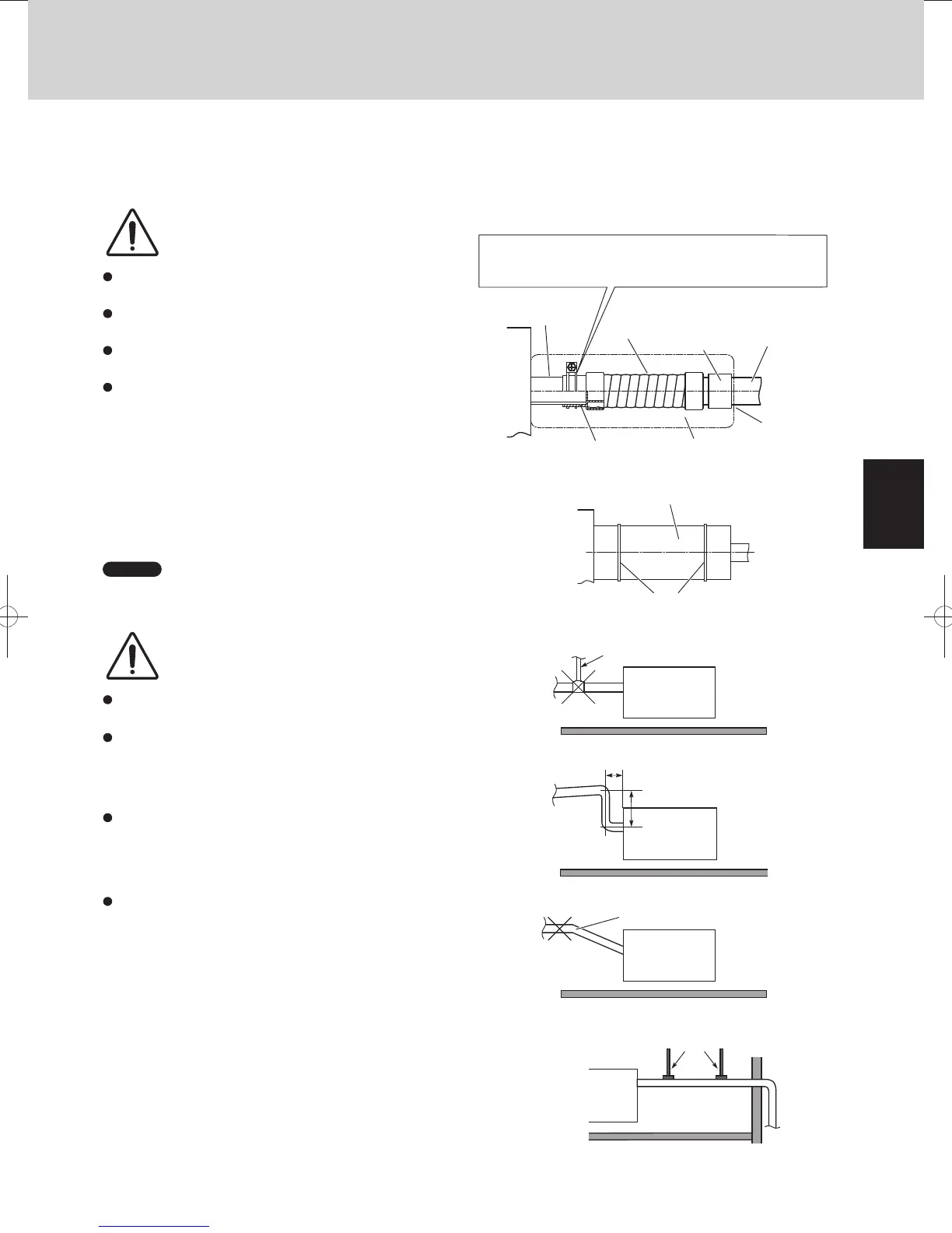
3-3-3. Installing the Drain Pipe
(1) Prepare standard hard PVC pipe (O.D. 32 mm) for the drain and use the supplied hose band to prevent water leaks.
The PVC pipe must be purchased separately.
The transparent drain part on the unit allows you to check drainage. (Fig. 2-46)
Do not use adhesive tape at the drain connection
port on the indoor unit.
Insert the drain pipe until it contacts the socket,
and then secure it tightly with the hose band.
Do not use the supplied drain hose bent at a 90°
angle. (The maximum permissible bend is 45°.)
Tighten the hose clamps so their locking nuts
face upward. (Fig. 2-46)
Align the wire of hose band without separating from the drain
hose and tighten so that it does not contact the bead.
Drainage check
section on drain port
(transparent)
Drain hose
(supplied)
Hard
PVC
socket
VP-25
(not supplied)
Hard
PVC pipe
VP-25
(not supplied)
Bead
Packing
(supplied)
PVC
adhesive
Fig. 2-46
(2) After connecting the drain pipe securely, wrap the supplied
packing and drain pipe insulator around the pipe, then secure
it with the vinyl clamps. (Fig. 2-47)
Drain insulator (supplied)
Vinyl clamps
(field supply)
Fig. 2-47
NOTE
Make sure the drain pipe has a downward slant
(1/100 or more) and that there are no water traps.
Do not install an air bleeder as this may cause water to
spray from the drain pipe outlet. (Fig. 2-48)
Prohibited
Air bleeder
Fig. 2-48
If it is necessary to increase the height of the drain pipe,
the section directly after the connection port can be raised a
maximum of 500 mm. Do not raise it any higher than
500 mm, as this could result in water leaks. (Fig. 2-49)
CAUTION
CAUTION
300 mm or less
500 mm or less
Good
Fig. 2-49
Do not install the pipe with an upward slant from the
connection port. This will cause the drain water to flow
backward and leak when the unit is not operating.
(Fig. 2-50)
Upward slant
Prohibited
Fig. 2-50
Do not apply force to the piping on the unit side when
connecting the drain pipe.
The pipe should not be allowed to hang unsupported
from its connection to the unit.
Fasten the pipe to a wall, frame, or other support as
close to the unit as possible. (Fig. 2-51)
Support pieces
Fig. 2-51
TDxxxxxx-002WAYVRF.indb25TDxxxxxx-002WAYVRF.indb25 2014/01/3017:52:312014/01/3017:52:31
 Loading...


