10
MG5000+ / MG5050+ Installation Guide
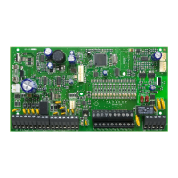
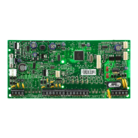
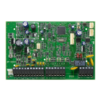
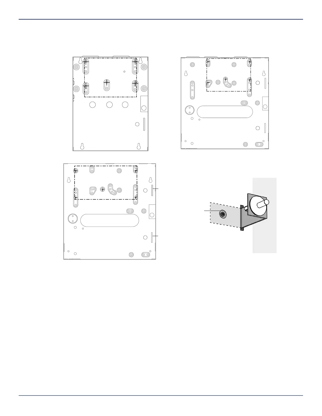
PCB Metal Box Installation
The crosses and dotted line represent the PCB mounting location. If you need specific dimensions, contact Paradox Distributor Support. For UL recommended
installation for the MG5000+ only, place the PCB one notch lower than the mounting location.
MG5000+ (8x10”) MG5000+ (11x11”)
MG5050+ (11x11”)
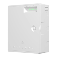
For EN compliancy use the Tamper Kit TK278. Insert into one of the
designated slots on the metal box and wire to an input.
Secure screw
to wall
Tamper Kit
Slot
Tamper Kit
Slot
Tamper Kit (TK278)