Model 3610 Installation
2-33610-A2-GB46-60 December 1996
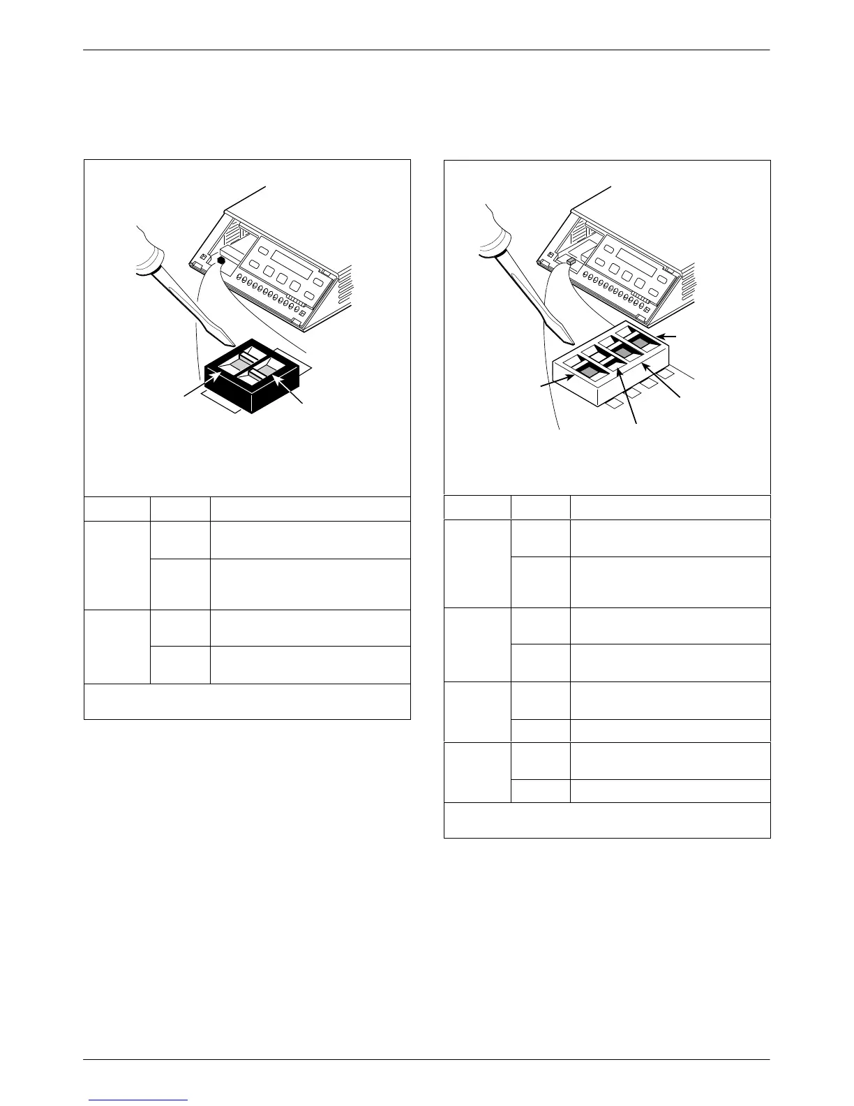
Figure A
496-14702-01
S1
ON
2
ON
l
Switch 1
V.32
Analog
DBM
Interface
(S1-1)
Frame Ground/
Signal Ground
(S1-2)
Switch Setting Function
S1-1
ON
(default)
Permissive transmit output level
of –9 dBm
V
.32
Analog
DBM only
OFF Programmable transmit output
level between –12 dBm and
0 dBm
ON Frame ground (FG) connected to
signal ground (SG)
S1-2
OFF
(default)
FG connected to SG through
100 ohm resistor
ON is to the rear as you face the front of the DSU.
OFF is to the front.
Figure B
496-14719-02
Switch 1
V.35
Test Mode
(S1-4)
EIA-232
Test Mode
(S1-3)
V.32
Analog
DBM
Interface
(S1-1)
Frame Ground/
Signal Ground
(S1-2)
S1
1
ON
2
3
4
1
2
3
4
Switch Setting Function
S1-1
ON
(default)
Permissive transmit output level
of –9 dBm
V.32
Analog
DBM only
OFF Programmable transmit output
level between –12 dBm and
0 dBm
ON Frame ground (FG) connected to
signal ground (SG)
S1-2
OFF
(default)
FG connected to SG through
100 ohm resistor
S1-3
ON
(default)
Enables EIA-232 Test mode;
Pin 25 controlled by the DSU
-
OFF Disables EIA-232 Test mode
S1-4
ON
(default)
Enables V.35 Test mode; V.35
lead NN controlled by the DSU
-
OFF Disables V.35 Test mode
ON is to the left as you face the front of the DSU.
OFF is to the right.