COMSPHERE 3600 Series Data Service Units
3-4 December 1996 3610-A2-GB46-60
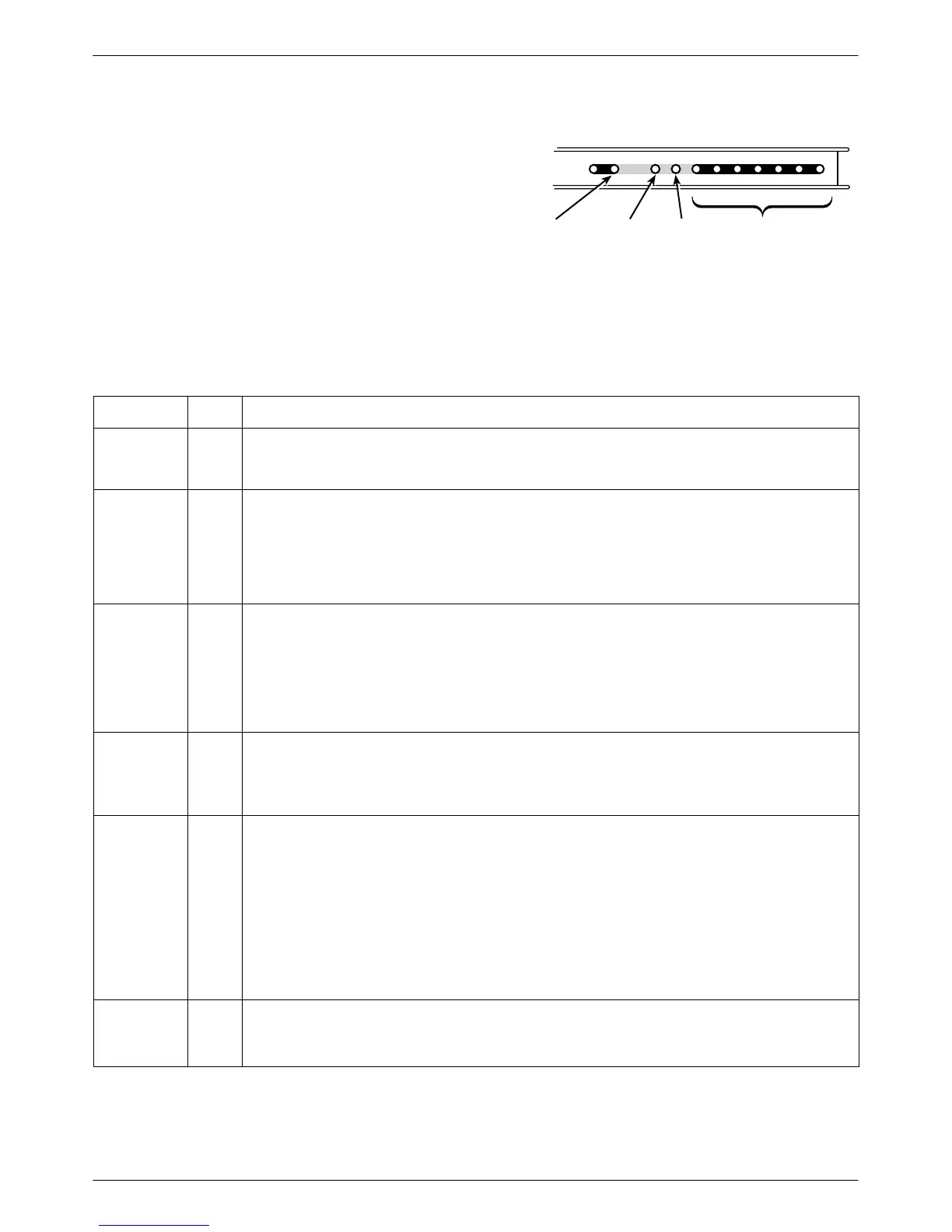
Status Indicators
Status indicators continuously provide information on
the current operating condition of the DSU or DBM.
T
able 3-1 describes all status indicators.
•
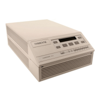
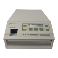
Model 3610 DSU status indicators appear on the
front panel.
• The carrier-mounted Model 361
1 status indicators
appear on the SDCP.
DTE Status
Indicators
Dial
Backup
Test
Mode
Network/Device
Alarm
496-14716-01
OK
Alrm
Test
Dial
TXD RXD
107
RTS CTS DTR LSDDSR
105 106 108 109104103
LEDs
Table 3-1
DSU Status Indicators
LED Label
Color Description
OK Green Health and status indicator: DSU operation is normal. The OK LED flashes two times per second
when a message from an NMS is present. When lit, the DSU has not detected any alarm listed
under Alrm, below.
Alrm Red Health and status indicator: There is an alarm in the local or remote DSU, DBM, or DDS facility, or
there is a corrupted configuration. For a DSU with TDM or MCMP, the alarm may be in the
communications path between the DSU and TDM or MCMP circuit card.
Alarms at the local or remote DSU cause the Alrm status indicator to light on the affected DSU.
Refer to Table E-5, Device Health and Status Messages, for further details. DBM health and
status messages are in Document No. 3610-A2-GB49.
Test Yellow When the active core is being tested, the active DSU or DBM device is either performing a test or
other DSUs or DBMs are in Test mode.
The DSU or DBM is automatically put into Test mode
when a remote DSU or DBM is performing a test disruptively. A DSU or DBM in Test mode has
the DTE interface turned Off.
DSU with TDM or MCMP: Any test involving the TDM or MCMP also involves the DSU. The test
is integrated into the DSU’s Health and Status report. When the active core is being tested, any
port included in the active core is also tested.
Dial Yellow DBM is active:
Rapid flashing: Call establish in progress
Slow flashing: Call established but in Standby mode
Steady ON: Backup call established and active
TXD, RXD,
RTS, CTS,
DSR, DTR,
LSD
Green DTE status indicators: Internal lead states at the DSU/DTE interface for circuit designations:
Control circuit active (CTS, DSR, DTR, LSD, and RTS)
or
Data circuit spacing (RXD and TXD)
DSU with TDM or MCMP: The circuit external lead states for any TDM or MCMP ports can be
selected through the front panel’s Control branch.
Model 3610 DSU: The monitored port is displayed on the front panel LCD.
Model 361
1 DSU with TDM or MCMP:
The TDM or MCMP faceplate indicates the monitored port with port LED lit.
DTR is always on. Refer to DTE Status on front panel for DTR status.
Front Panel
(Model 361
1
only)
Yellow The currently selected DSU at the SDCP: The SDCP addresses one DSU at a time.
Model 361
1 DSU with TDM or MCMP: The TDM or MCMP circuit card has the same address as
the associated DSU and is also addressed.