COMSPHERE 3600 Series Data Service Units
2-10 December 1996 3610-A2-GB46-60
To
install the hubbing device:
. Procedure
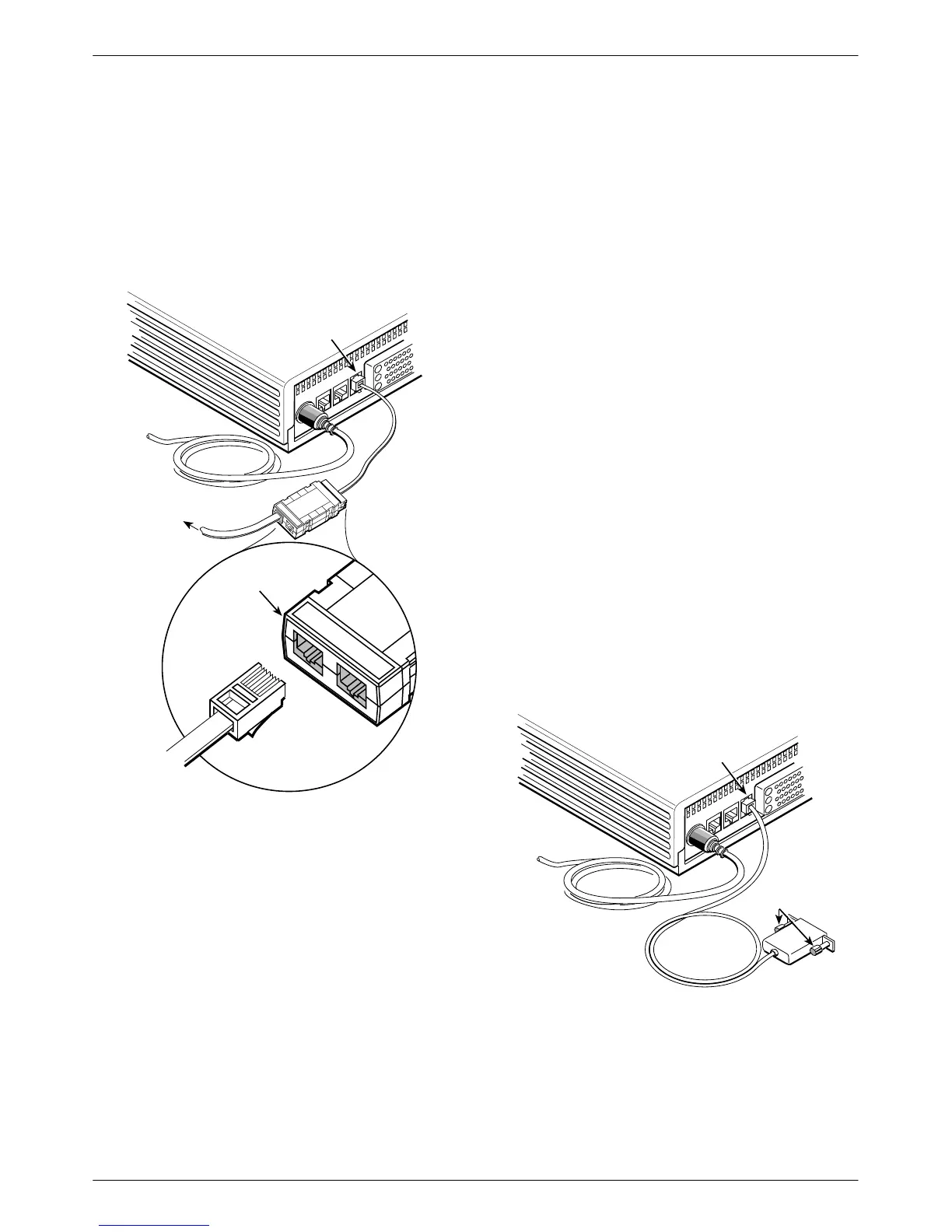
1. Plug the 4-pin modular plug of the hubbing device
into the modular jack labeled CC/DC
located on
the rear of the DSU.
496-14723-0
NMS Network
Connection
CC/DC
Hubbing
Device
To
NMS
POWER
LINE
BACKUP
CC/DC
V.35
CC IN/DC OUT
3000HUBBING DE
MODEL #3000-F3
CC IN/DC OUT
CC OUT/DC IN
M6BJ
Cable
3000HUBBING DEVICE
MODEL #3000-F3-300
2. Plug one end of the 6-pin cable into the hubbing
device jack labeled
CC IN/DC OUT
.
3.
Plug the opposite end of the M6BJ cable into the
appropriate 6700 or 6800 Series NMS jack.
Refer to your COMSPHERE 6700 or 6800 Series
NMS documentation to control and configure the DSU
from the NMS.
SNA Diagnostic Interface Verification
. Procedure
1. Enable the LPDA option (refer to Table 4-5).
2. Send a DSU/CSU and Line Status test from the
IBM NetV
iew console to the control DSU and
each tributary.
3.
As the status for each DSU is returned to NetV
iew,
check the network address. If the address is
correct, the verification procedure is complete.
Refer to Appendix D,
SNA Diagnostics
, for
additional configuration information.
Async
T
erminal Connection
Use
a CC-to-DB25 cable to connect an async terminal
to a DSU. This feature is available for the Model 3610
standalone unit only
. T
o enable the async terminal, see
Appendix C,
Async T
erminal Operation
.
. Procedure
1. Plug the 4-pin modular plug of the DSU
CC-to-DB25 cable (feature number 3600-F3-504)
into the DSU jack labeled CC/DC.
Async Terminal
Connection
495-14577-02
To Async
Terminal
CC/DC
POWER
LINE
BACKUP
CC/DC
V.35
Holding
Screws
2. Connect the EIA-232 (DB25) end of the cable to
the async terminal. T
ighten the holding screws.