COMSPHERE 3600 Series Data Service Units
2-2 December 1996 3610-A2-GB46-60
Installation Process
• Verifying the S1 Switch Settings
• Powering Up the DSU
• Connecting to the DDS Network
• Network Verification Testing
• DTE Connections
DSU Installation Planning
The
Model 3610 DSU is designed for desktop
operation.
• Place the DSU in the planned location.
• Allow 1 to 2 feet of clearance for cable
connections, space for the ventilation slots on the
sides, and clearance at the rear for the cable
connections.
• V
erify the S1 switch settings as indicated below
.
Verifying the S1 Switch
Settings
HANDLING
PRECAUTIONS
FOR
STA
TIC-SENSITIVE DEVICES
This product is designed to
protect sensitive components
from damage due to electrostatic
discharge (ESD) during normal
operation. When performing
installation procedur
es, however
,
take proper static control
precautions to prevent damage to
equipment. If you are not sure of
the proper static control
precautions, contact your nearest
sales or service r
epresentative.
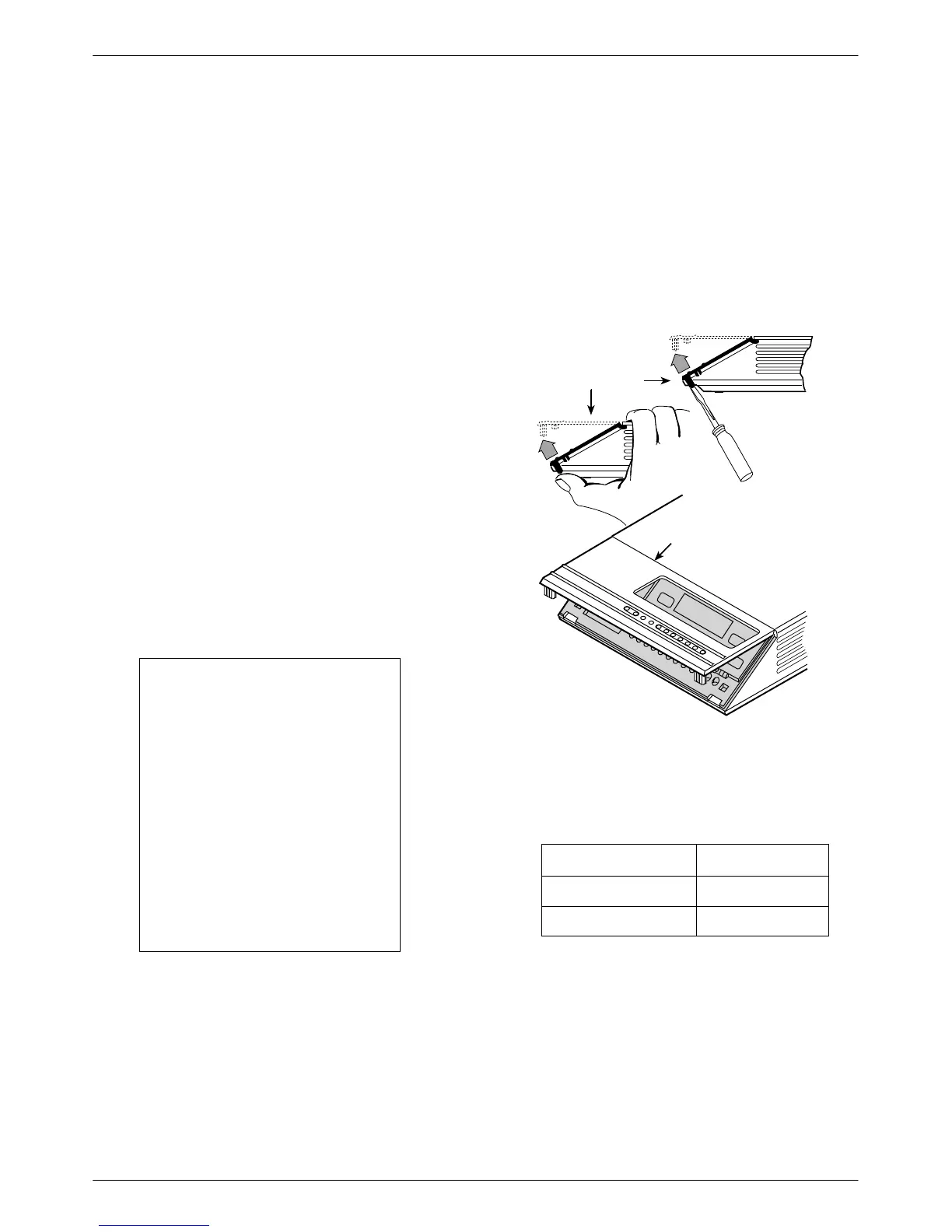
The Model 3610 DSU has a switch located under the
front panel. To verify or change the S1 switch settings,
remove the front bezel:
. Procedure
1. Place a small screwdriver or your thumbs under
the two tabs on the outside edges of the front
bezel. Firmly press upward to separate the bezel
from the tabs.
496-14701-0
Front Bezel
COMSPHERE 3610
Front Bezel
or
2. Swing the front bezel up and set aside.
3.
Change the switch settings if necessary
. Use a
small instrument. Do not use a pencil.
If the DSU has . . . Then use . . .
Two switches Figure A.
Four switches Figure B.
4. Reinsert the front bezel’
s hinge tabs into position
at the top and swing the bezel down. Snap the
bezel back into place.