10 of 20
598P/599P Application Manual
598/599P Set-up Procedure
At the moment the software identifies the 590P External Stack Module as a 590PH Module and therefore the
External Stack must be set for a similar current range to an equivalent 590PH.
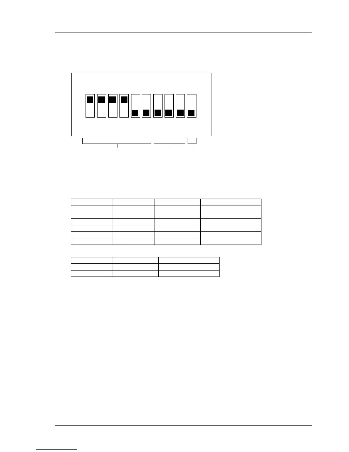
CALIBRATION SWITCH
1 2
3
4 5 6 7 8 9 10
500 amp Steps
If Cal
V a Cal
ON
4 Sw i t ches On
ARMATURE CURRENT CALIBRATION
4 Switches must be “On” under ALL circumstances. The Drive Software will then scale the Current Feedback
Signal to give the desired Output Current provided the correct ACCTs of a ratio of 2000 to 1 have been fitted.
FIELD CURRENT CALIBRATION
ARMATURE VOLTAGE CALIBRATION
Example
Set the Product Code of the Module to a 590H of the same Current Range as the Stack and with the associated
maximum field current calibration. i.e. for a 2Q Stack with a 2000 Amps Armature and a 35 Amps Field set the
Product Code to DC 2Q 2200A 40 D
Set the Field Calibration switches to the appropriate range i.e. with SW7 OFF, SW8 OFF & SW9 ON.
Adjust the Armature Current and other parameters as normal provided the external CT is 2000:1.
For a different CT Ratio “R” set the Armature Current using an appropriate multiplier where the multiplier M =
2000/R and the Armature Current Setting is M * Normal. i.e. if the CT Ratio is 1000:1 you will need to set 2 *
the required current. Note this may mean that you may have to select a Higher Current Range on the Initial
Product.
This manual was downloaded on www.sdsdrives.com
+44 (0)117 938 1800 - info@sdsdrives.com