Cont. 3
598P/599P APPLICATION MANUAL
Contents
Overview ......................................................................................................... 1
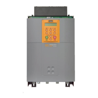
Outline Drawing ............................................................................................... 1
Electrical Installation ......................................................................................... 2
3-Phase Contactor ...................................................................................................... 2
Auxiliary Supply .......................................................................................................... 2
Semiconductor Fuses ................................................................................................... 2
Current Transformers .................................................................................................. 2
Heatsink Thermostats .................................................................................................. 2
PROTECTION OF STACK CONTROL AND FEEDBACK WIRING ................................... 3
THYRISTOR TRIGGER OUTPUT OPTIONS .................................................................... 3
1. Trigger Board Output Option ....................................................................... 3
2. Amplifier Output Option ............................................................................... 5
Power Connections ........................................................................................... 6
Minimum Connection 4Q Stack Trigger Board Option ............................................ 6
Minimum Connection 2Q Stack Trigger Board Option ............................................ 7
Pulse Amplifier Connections 4Q Stack .................................................................... 8
Power Amplifier Connections 2Q Stack ................................................................... 9
598/599P Set-up Procedure ............................................................................ 10
Calibration Switch .....................................................................................................10
Armature Current Calibration ....................................................................................10
Field Current Calibration ...........................................................................................10
Armature Voltage Calibration ....................................................................................10
Technical Specification .................................................................................... 11
Environmental Data ..................................................................................................11
Electrical Ratings .......................................................................................................11
Field Fusing ..............................................................................................................11
Thyristor Wiring .............................................................................................. 12
Standard Trigger Board Terminal Assignment ............................................................12
4 Quad ...............................................................................................................12
2 Quad ...............................................................................................................12
Optoisolator Trigger Board Terminal Assignment .......................................................13
4 Quad ...............................................................................................................13
2 Quad ...............................................................................................................13
Optoisolator Firing Board Terminal Layout and Dimensions .......................................14
Version 1 .............................................................................................................14
Version 2 .............................................................................................................15
Product Code ................................................................................................. 16
Legacy Product Code ................................................................................................17
CERTIFICATION ............................................................................................. 18
Europe ......................................................................................................................18
CE Marking for the Low Voltage Directive (LVD) 2006/95/EC ...............................18
CE Marking for the EMC Directive 2004/108/EC ..................................................19
EMC General Installation Considerations ..............................................................19