ACR7000 Stepper User Guide
Encoder Feedback Connectors
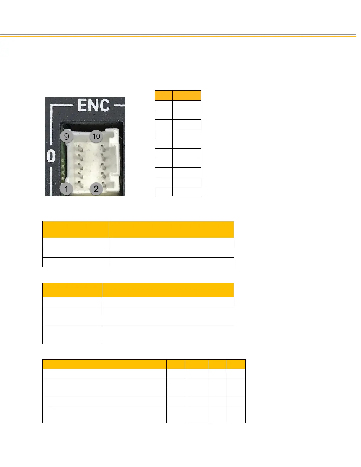
The Encoder feedback connectors provide inputs for incremental encoders. Each encoder connector is dedicated
to a specific ENCODER object that can be assigned to axes within the software.
Pin Signal
1 A+
2 A-
3 B+
4 B-
5 Z+
6 Z-
7 5V
8 GND
9 Earth
10 Earth
Encoder Connector Specification
Description Specification
Connector Type
10 Pin, MicroClasp Header, 2mm pitch
Manufacturer Molex or equivalent
Molex 55959-1030
Encoder Connector Specification—Mating Connector(not inlcuded with product)
Description Specification
Connector Type 10 Pin, 2.00mm Pitch MicroClasp
Manufacturer Molex or equivalent
Connector Housing:
Molex Part Number 51353-1000
Contacts Crimp terminal 22-28 AWG
Molex part number : 56134-9100
Encoder Inputs
Description Min Typical Max Units
Common Mode Range -7
+7 V
Current—Encoder
50mA 250 mA
Differential Threshold Voltage -200
+200 mV
Differential Termination Impedance
120
ohms
Maximum Encoder Input Frequency
(pre-quadrature)
1.6 MHz

 Loading...


