17
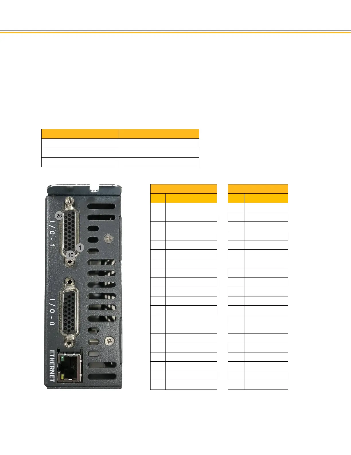
I/O Connections
Each 26-pin Drive I/O connector includes ten inputs and four outputs. Input and output signals are NOT optically
isolated.
Connecter I/O - 0 also included the dedicated Motion Enable Input.
Inputs are pulled up to 24V supply. Sink the inputs to ground to assert.
Four sinking outputs are available to the user. Total current of 1 amp is available using 24VDC from PIN 19.
Parker breakout modules VM26-PM can be used for easy access to these pins.
I/O - 0 I/O - 1
Inputs 0-5, Trigger inputs 24-27 Inputs 6-11, Trigger inputs 28-31
Outputs 32-35 Outputs 36-39
I/O Connector 0
1 Input 0
2 Input 1
3 Input 2
4 Input 3
5 Input 4
6 Input 5
7 Input 24
8 Input 25
9 Input 26
10 Input 27
11 GND
12 Output 32
13 Output 33
14 Output 34
15 Output 35
16 GND
17 Motion Enable Input
18 GND
19 24VDC - output
20-26
GND
I/O Connector 1
1 Input 6
2 Input 7
3 Input 8
4 Input 9
5 Input 10
6 Input 11
7 Input 28
8 Input 29
9 Input 30
10 Input 31
11 GND
12 Output 36
13 Output 37
14 Output 38
15 Output 39
16 GND
17 GND
18 GND
19 24VDC - output
20-26 GND

 Loading...


