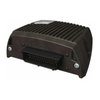
ACR7000 Stepper User Guide
Stepper Drive Operation
The integrated stepper drives in the ACR7000 are configured using the Configuration Wizard in Parker Motion
Manager Software. The necessary flags and parameters are included in the controller configuration and
downloaded as part of the user project along with scaling, limits, program memory settings, etc. The following
provides detail about these drive settings how the drives operate.
The values required to properly control and configure the drives are stored in axis specific parameters. These
values are saved with the ESAVE command and are automatically restored on power up. The values are
automatically asserted to the integrated drive on power up. The parameter values may be changed by the user
during operation, but will not be asserted to the integrated drive until the user sets a control bit requesting
configuration update.
During power up and during any configuration update, a status bit will indicate that an update is underway. When
the drive configuration update is complete, a different bit will indicate that configuration is complete.
If any of the configuration values provided by the user are out of range, then the user’s configuration request or
the power up configuration will fail and the integrated drive will be configured with the product’s default values.
In this case a status bit will indicate the failure and an error code will indicate the reason for failure.
Fault and warning flags are available and can be used to diagnose improper operation. If any fault flag is present,
it will be latched and result in a drive fault, disabling the drive. The latched bit is cleared by re-enabling the drive.
The control bits clear themselves automatically.
Applying Drive Settings
Drive configuration settings (motor current, resolution, standby current and delay) are applied either on power-up
or when the axis Assert Drive Configuration flag is SET. The configuration values should be saved with the ESAVE
command to be retained on power cycle. In a typical set-up sequence the motor current, resolution and standby
values would be set for the axis, followed by the Assert Drive Configuration flag. For example:
REM AXIS0 Settings
P7938= 1.5 : REM User Maximum motor current (Amps)
P7944= 50 : REM Standby Current Percentage
P7945= 10 : REM Standby Current Delay (msec.)
SET 15618 : REM Enable Auto Standby
P7945= 128 : REM Micro-steps per full step (power of 2) = 25600
SET 15616 : REM Apply Drive Configuration settings
ESAVE : REM save value to retained memory
Motor Current
The maximum motor current available for each axis is 4.0 amps. The user can specify a value to limit the current
applied to the motor. The minimum setting for drive current is 0.5. This current value a peak of sine rating.

 Loading...


