13
Input Power Connections
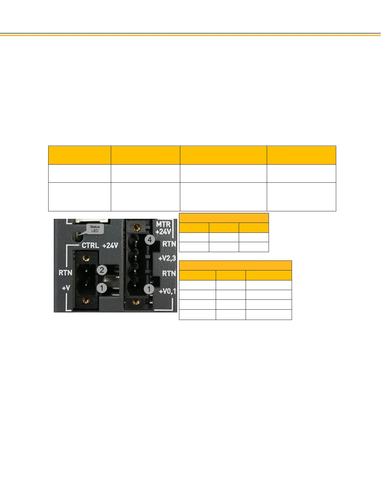
Separate power inputs are required for the motors and control power. Motors power inputs are shared by two
motors. Control Power is necessary for all logic and communication.
Removable mating connectors are provided with the product.
CAUTION: Before inserting or removing any connectors or wires, always remove power from the unit.
Input Power Requirements
Connector Input Power Requirements Functions
MTR +24V Motor Input Power 24VDC @ 0.75 x Motor Rated
Current
Motor Power
CTRL Control Input Power 24VDC @ 1 amp Communications
Diagnostics
Encoder feedback
CTRL
2
RTN
GND24V
1
+V
+24VDC
MTR +24V
4
RTN
GND24V
3
+2,3
Motor 2/3 PWR
2
RTN
GND24V
1
+0,1
Motor 0/1 PWR

 Loading...


