15
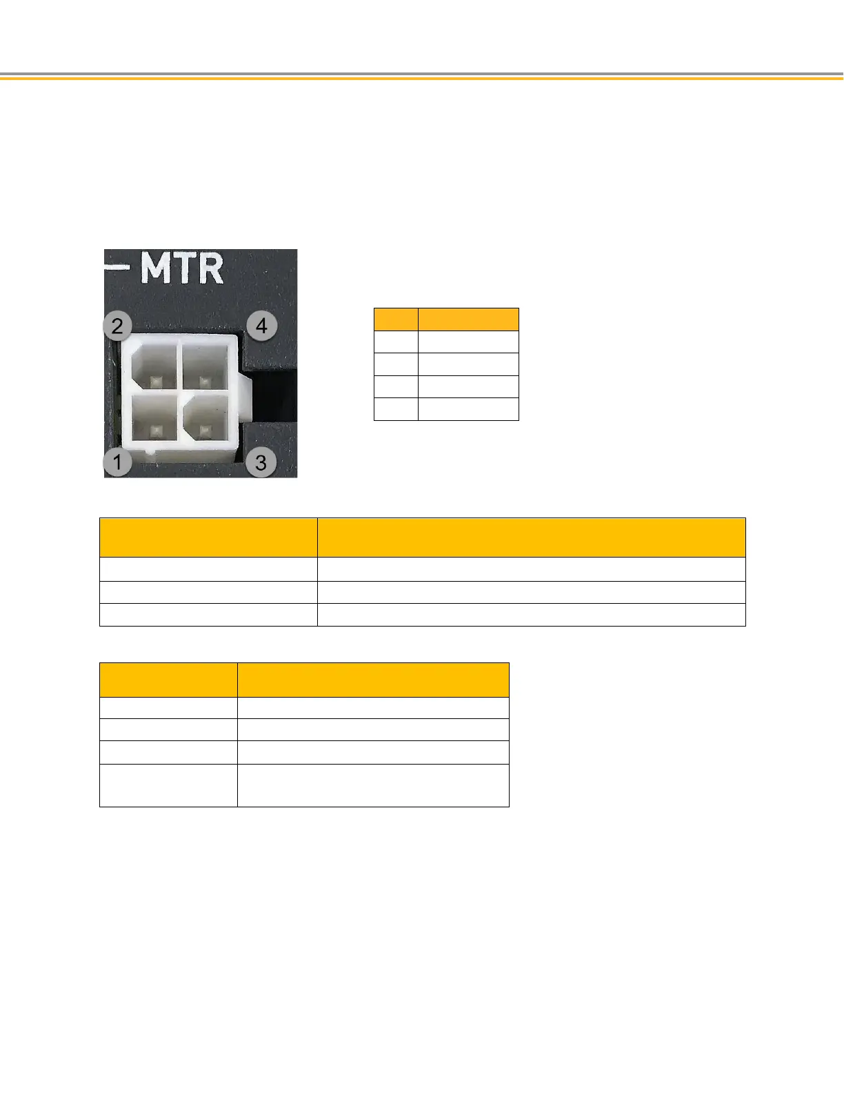
Motor Output Connectors
The Motor power connectors provide output power to the two phase stepper motors. The number of activated
motor connectors is dependent on the controller configuration. Each Motor connector is dedicated to a specific
AXIS object that controls the output signal.
CAUTION: Before inserting or removing any connectors or wires, always remove power from the unit.
-)
-)
Motor Connector Specification
Description Specification
Connector Type
4 Pin, Mini-Fit Jr. Header
Manufacturer Molex or equivalent
Molex 5569-04A2-210/39-30-0040
Motor Connector Specification—Mating Connector*
Description Specification
Connector Type 4 Pin, Mini-Fit Jr. Receptacle housing
Manufacturer Molex or equivalent
Connector Housing:
Molex Part Number 5557-04R-210/39-01-2045
Contacts Mini-Fit Female crimp terminal
Molex part number : 5556T/39-00-0038
*Not included with product

 Loading...


