Parker EME
Compax3F device description
192-121100 N6 June 2008 15
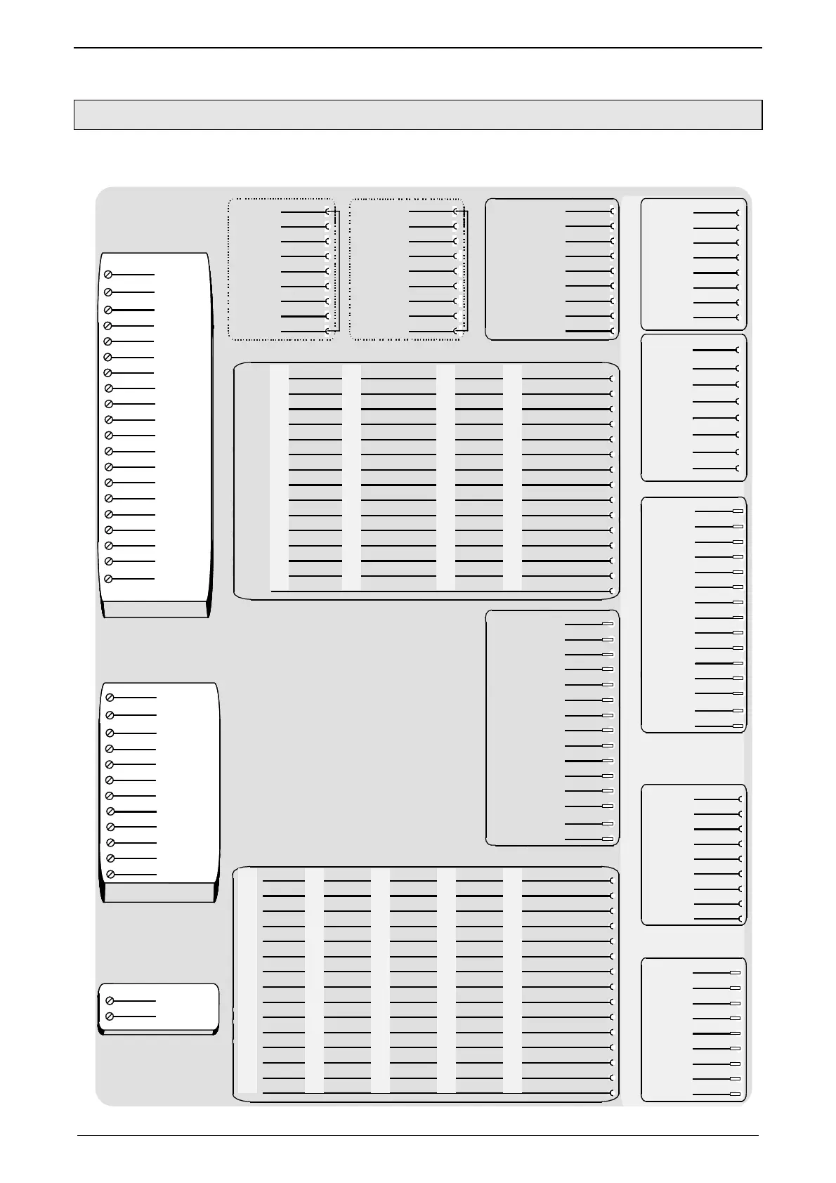
3.2.3. Plug and connector assignment complete
The fitting of the different plugs depends on the extension level of Compax3.
In part, the assignment depends on the Compax3 option implemented.
X13/1
X13/2
X13/3
X13/4
X13/5
X13/6
X13/7
X13/8
X13/9
X13/10
X13/11
X13/12
X13/13
X13/14
X13/15
X10/2
RxD
X10/3
TxD
X10/4
DTR
X10/5
GND
X10/6
DSR
X10/7
RTS
X10/8
CTS
X10/9
+5V
X
1
0
:
R
S
2
3
2
X10/1
EnableRS232 0V
X
1
2
:
D
i
g
i
t
a
l
I
n
p
u
t
s
/
O
u
t
p
u
t
s
X12/1
X12/2
X12/3
X12/4
X12/5
X12/6
X12/7
X12/8
X12/9
X12/10
X12/11
X12/12
X12/13
X12/14
X12/15
Output+24V
Output0
Output1
Output2
Output3
Input0
Input1
Input2
Input3
Input4
Input+24V
Input5
Input6
Input7 or (MN-INI)
GND24V
X11/1
X11/2
X11/3
X11/4
X11/5
X11/6
X11/7
X11/8
X11/9
X11/10
X11/11
X11/12
X11/13
X11/14
X11/15
X23/6
+5V
X23/7
res.
X23/8
Data line-A
X23/9
res.
X
2
3
:
P
r
o
f
i
b
u
s
X23/1
res.
X23/2
res.
X23/3
Data line-B
X23/4
RTS
X23/5
GND
X23/6
res.
X23/7
CAN_H
X23/8
res.
X23/9
res.
X
2
3
:
C
A
N
o
p
e
n
X23/1
res.
X23/2
CAN_L
X23/3
GNDfb
X23/4
res.
X23/5
SHIELD
X22/1
X22/2
X22/3
X22/4
X22/5
X22/6
X22/7
X22/8
X22/9
X22/10
X22/11
X22/12
X22/13
X22/14
X22/15
res.
O0/I0
O1/I1
O2/I2
O3/I3
O4/I4
O5/I5
O6/I6
O7/I7
O8/I8
Input24VDC
O9/I9
O10/I10
O11/I11
InputGND
X
2
2
:
I
n
p
u
t
/
O
u
t
p
u
t
o
p
t
i
o
n
M
1
2
(
M
1
0
=
+
H
E
D
A
)
H
E
D
A
-
m
o
t
i
o
n
b
u
s
o
p
t
i
o
n
M
1
1
(
M
1
0
=
+
I
/
O
s
)
X20/6
Lx/
X20/7
res.
X20/8
res.
X
2
0
:
H
E
D
A
i
n
X20/1
Rx
X20/2
Rx/
X20/3
Lx
X20/4
res.
X20/5
res.
24V
GND
IN0+
X1
X21/6
Lx/
X21/7
res.
X21/8
res.
X21/1
Tx
X21/2
Tx/
X21/3
Lx
X21/4
res.
X21/5
res.
X
2
1
:
H
E
D
A
o
u
t
Analog Input
X10/2
X10/3
X10/4
X10/5
X10/6
X10/7
X10/8
X10/9
X10/1
RxD
TxD/
res.
GND
res.
TxD
RxD/
+5V
RS485 +5V
X
1
0
:
R
S
4
8
5
v
ie
r
d
r
a
h
t
X10/2
X10/3
X10/4
X10/5
X10/6
X10/7
X10/8
X10/9
X10/1
res.
TxD_RxD/
res.
GND
res.
TxD_RxD/
res.
+5V
RS485 +5V
X
1
0
:
R
S
4
8
5
z
w
e
id
r
a
h
t
Analog Output
GND24V
+24V
X3/1
X3/2
X3
24VDC power supply
X1/1
X1/2
X1/3
X1/4
X1/5
X1/6
X1/7
X1/8
X1/10
X1/11
X1/12
X1/13
X1/18
X1/19
X1/20
X1/15
X1/16
X1/17
X1/14
X1/9
X2/1
X2/2
X2/3
X2/4
X2/5
X2/6
X2/7
X2/8
X2/10
X2/11
X2/12
X2/9
I/U out0
GND0
I/U out1
GND1
I/U out2
GND2
I/U out3
GND3
Iout0
GND
Iout1
GND
X2
Compax3F
IN0-
24V
GND
IN1+
IN1-
24V
GND
IN2+
IN2-
24V
GND
IN3+
IN3-
IN4+
IN4-
IN5+
IN5-
X13: 1.Feedback system
X11: 2.Feedback system
+24V +24V
Sense+ Sense+ Sense+
Sin+ Sin+
Vcc(+5V) Vcc(+5V) Vcc(+5V)
+5V +5V +5V
A- INIT- Clock- Clock-
A+ INIT+ Clock+ Clock+
B+ STSP+ COS+ COS+
SIN- SIN-
Sense - Sense- Sense-
B- STSP- COS- COS-
N- N- DATA- DATA-
N+ N+ DATA+ DATA+
R
S
4
2
2
E
n
c
o
d
e
r
GND
S
t
a
r
t
/
S
t
o
p
GND
S
i
n
u
s
C
o
s
i
n
u
s
1
V
S
S
GND
E
n
D
a
t
2
.
1
GND
S
S
I
GND
24V 24V
Aout1
Aout0
+5V
A- INIT- Clock-
A+ INIT+ Clock+
B+ STSP+
B- STSP-
N- DATA-
N+ DATA+
D
A
-
M
o
n
i
t
o
r
GND
R
S
4
2
2
E
n
c
o
d
e
r
GND
S
t
a
r
t
/
S
t
o
p
GND
S
S
I
GND
In detail:

 Loading...


