Parker EME
Compax3F device description
192-121100 N6 June 2008 21
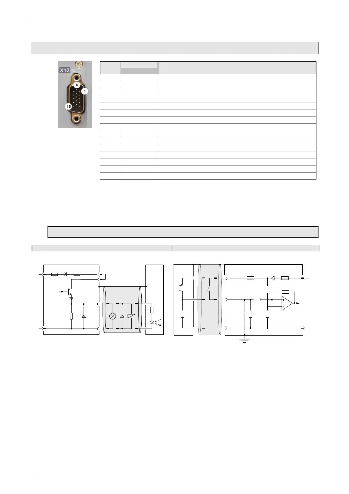
3.2.9. Digital inputs/outputs (plug X12)
X12
Pin
Input/output I/O /X12
High density/Sub D
1 Output +24VDC output (max. 340mA)
2 O0 Output 0 (max. 100mA)
3 O1 Output 1 (max. 100mA)
4 O2 Output 2 (max. 100mA)
5 O3 Output 3 (max. 100mA)
6 I0 Input 0
7 I1 Input 1
8 I2 Input 2
9 I3 Input 3
10 I4 Input 4
11 E 24V input for the digital outputs Pins 2 to 5
12 I5 Input 5
13 I6 Input 6
14 I7 Input 7
15 Output Gnd 24 V
All inputs and outputs have 24V level.
The exact assignment depends on the the device type!
You will find the description of the device-specific assignment in the online help
which can be opened from the Compax3 – ServoManager.
Maximum capacitive loading of the outputs: 50nF (max. 4 Compax3 inputs).
3.2.9.1 Connection of the digital Outputs/Inputs
Wiring of digital outputs Status of digital inputs
24V
0V
X12/2
18.2K
Ω
X12/15
X12/1
X12/11
SPS/
PLC
F2
F1
Compax3
24V
0V
100K
Ω
X12/1
X12/6
X12/15
10K
Ω
22K
Ω
22K
Ω
22K
Ω
SPS/PLC
F2
F1
10nF
Compax3
The circuit example is valid for all digital outputs!
The outputs are short circuit proof; a short circuit
generates an error.
The circuit example is valid for all digital inputs!
Signal level:
> 9.15V = "1" (38,2% of the control voltage applied)
> 8.05V = "0" (33.5% of the control voltage applied)
F1: delayed action fuse
F2: quick action electronic fuse; can be reset by switching the 24VDC supply off and on again.

 Loading...


