EasyManuals Logo

Parker Compax3 Start-Up

Parker Compax3
40 pages
To Next Page IconTo Next Page
To Previous Page IconTo Previous Page
Page #6 background imageLoading...
Page #6 background image
START UP
6 192-120112 N1 C3 Start up March 2004
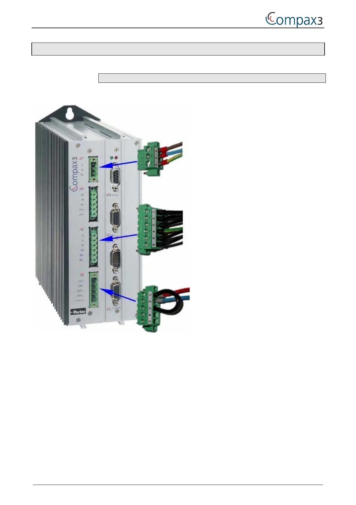
1.2.2. Required wirings
Connections of Compax3
For V2 device
X1 230VAC
Pin1 = L
Pin2 = N
Pin3 = PE
For V4 device
X1 400VAC
Pin1 = L1
Pin2 = L2
Pin3 = L3
Pin4 = PE
X3 Motor
Pin1 = U
Pin2 = V
Pin3 = W
Pin4 = PE
Pin5 = Motor holding brake BR +
Pin6 = Motor holding brake BR –
ATTENTION!
Pin 5+6 must only be wired in the case of a motor
that is equipped with a brake! Otherwise make no
brake connections at all.
X4 24VDC enable
Pin1 = +24VDC
Pin2 = GND
Pin3 = +24VDC (ENAin)

Other manuals for Parker Compax3

Questions and Answers:

Question and Answer IconNeed help?

Do you have a question about the Parker Compax3 and is the answer not in the manual?

Parker Compax3 Specifications

General IconGeneral
Protection ClassIP20
Control ModesTorque, Speed, Position
Feedback OptionsIncremental encoder, Absolute encoder, Resolver
Communication InterfacesCANopen, EtherCAT, Profinet
Safety FeaturesSTO (Safe Torque Off), SS1 (Safe Stop 1), SOS (Safe Operating Stop)
Input Voltage200-480 VAC
Relative Humidity5% to 85% (non-condensing)
Shock ResistanceAccording to EN 60068-2-27
Operating Temperature0°C to +40°C

Related product manuals