EasyManuals Logo

Parker PHD Series User Manual

Parker PHD Series
58 pages
To Next Page IconTo Next Page
To Previous Page IconTo Previous Page
Page #19 background imageLoading...
Page #19 background image
11
Connectors
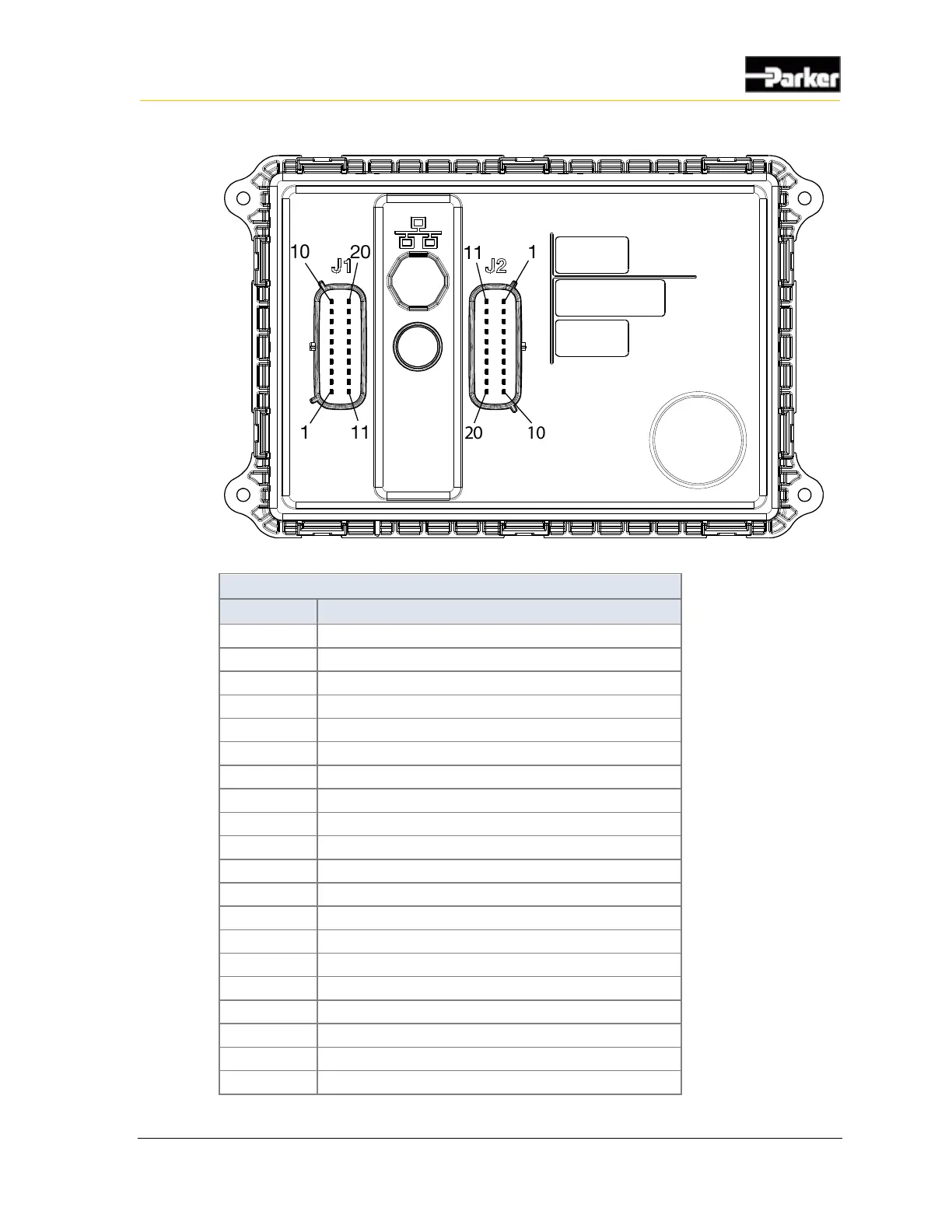
Figure 5: Back of PHD70 showing connectors
PHD70 J1 Connector Pinout
Pin
Function
1
GPIO7 (digital input/low power output)
2
GPIO1 (digital input/low power output)
3
GPIO6 (digital input/low power output)
4
OUTPUT2 (low-side output)
5
CAN1_TERM (CAN termination)
6
CAN1_SHLD (CAN shield)
7
CAN1_L (CAN low)
8
CAN1_H (CAN high)
9
GND (Negative battery)
10
+VBATT (Positive battery)
11
GPIO5 (digital input/low power output)
12
GPIO4 (digital input/low power output)
13
GPIO3 (digital input/low power output)
14
GPIO2 (digital input/low power output)
15
USB_D-
16
USB_D+
17
USB_GND
18
USB_VBUS (5V supply)
19
P12V0 (12V regulated supply)
20
OUTPUT1 (low-side output)

Questions and Answers:

Question and Answer IconNeed help?

Do you have a question about the Parker PHD Series and is the answer not in the manual?

Parker PHD Series Specifications

General IconGeneral
BrandParker
ModelPHD Series
CategoryControl Unit
LanguageEnglish

Related product manuals