43
What
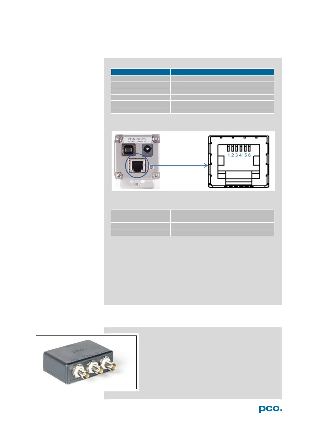
A1.3 PINOUT OF RJ11 CONNECTOR
+12V (alternative power supply)
Pin
P
os
i
t
i
on
Timing &
S
i
gn
a
l
s
camera is recording or sensor readout
in progress
external trigger is ready to
a
cc
e
p
t
In Auto Sequence trigger mode the busy signal is always set to
TRUE, while the exposure signal indicates the real exposure of the
image sensor.
In External Exp. Start trigger mode the camera is ready to accept a
new trigger signal on PIN #5 (trigger) when the busy signal is set to
FALSE. After a successful trigger event the busy signal stays TRUE
until the exposure is finished and the image is completely read out.
A2 TRIGGER INTERFACE
Connect the trigger interface to the RJ11-Connector of
your camera. It is equipped with three BNC outs
(Trigger / Busy / Exposure). The trigger interface is just
a connection adapter from RJ 11 to BNC without any
active electronics.
For more information confirming trigger modes see A1.3
and 6.3.1.