Note that all event registers and the status
byte record positive events. That is when
a condition changes from inactive to ac
-
tive, the bit in the event register is set
true. When the condition changes from
active to inactive, the event register bits
are not affected at all.
When you read the contents of a register,
the counter answers with the decimal sum
of the bits in the register.
Example:
The counter answers 40 when you ask for
the contents of the Standard Event Status
Register.
–
Convert this to binary form. It will give
you 101000.
–
Bit 5 is true showing that a command error
has occurred.
Using the Subsystems
Status Subsystem 6-11
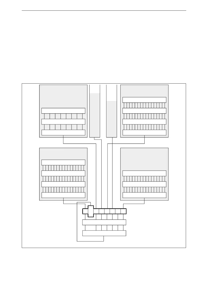
Logical OR
Enable Register
Event Register
Standard Event Register
Service Request Enable
Logical OR
Status Byte Register
Logical OR
Condition Register
Condition Register
SRQ message
Device Register 0
Operation Status Register
Questionable Data Register
01234567
Error Queue
Output Queue
Enable Register
Event Register
Enable Register
Event Register
Logical OR
Event Register
Enable Register
Logical OR
Figure 6-2 Model ‘9X’ status register structure.