Input Signaling Conditioning
The digital LP filter utilizes the Hold-Off
function described below.
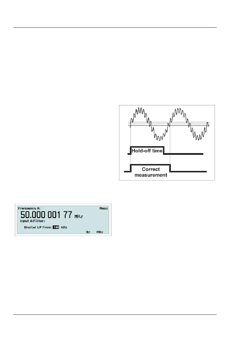
With trigger Hold-Off it is possible to insert a
deadtime in the input trigger circuit. This
means that the input of the counter ignores all
hysteresis band crossings by the input signal
during a preset time after the first trigger
event.
When you set the Hold-Off time to approx.
75% of the cycle time of the signal, erroneous
triggering is inhibited around the point where
the input signal returns through the hysteresis
band. When the signal reaches the trigger point
of the next cycle, the set Hold-Off time has
elapsed and a new and correct trigger will be
initiated.
Instead of letting you calculate a suitable Hold-
Off time, the counter will do the job for you by
con
verting the filter cutoff frequency you enter
via the value input menu below to an
equivalent Hold-Off time.
Fig. 3-7 Value input menu for setting the cutoff
frequency of the digital filter.
You should be aware of a few limitations to be
able to use the digital filter feature effectively
and unambiguously. First you must have a
rough idea of the frequency to be measured. A
cutoff frequency that is too low might give a
perfectly stable reading that is too low. In such
a case, triggering occurs only on every 2nd,
3rd or 4th cycle. A cutoff frequency that is too
high (>2 times the input frequency) also leads
to a stable reading. Here one noise pulse is
counted for each half-cycle.
Use an oscilloscope for verification if you are
in doubt about the frequency and waveform of
your input signal.
The cutoff frequency setting range is very
wide: 1 Hz - 50 MHz
Digital LP filter operates in the measuring
logic, not in the input amplifier.
Toggle between manual and automatic trigger-
ing with this softkey. When
Auto is active the
counter automatically measures the
peak-to-peak levels of the input signal and sets
the trigger level to 50% of that value. The
attenuation is also set automatically.
At rise/fall time measurements the trigger lev-
els are automatically set to 10% and 90% of
the peak values.
When
Manual is active the trigger level is set
in the value input menu designated
Trig. See
below. The current value can be read on the
display before entering th
e menu.
USER MANUAL ● CNT 9x Series ● Rev.22 February 2020
3-4