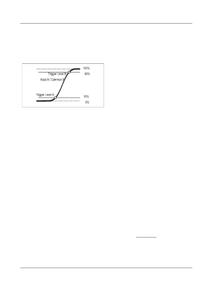
The counter measures the time from when the
signal passes 10 % of its amplitude to when it
passes 90 % of its amplitude. The trigger lev-
els are calculated and set automatically.
Auxiliary parameters shown simultaneously
are Slew Rate (V/s), Vmax and Vmin
Trigger levels for rise/fall mea-
surements.
For ECL circuits, the reference levels are 20
% (start) and 80 % (stop). In this case you can
use either of two methods:
1. Select the general Time Interval function
described above and set the trigger levels man-
ually after calculating them from the absolute
peak values. Then you can benefit from the
auxiliary parameters Vmax and Vmin. For
measurements made on input A, use the fol-
lowing settings:
Rise
Time:
Trig Level A = V
min +0.2(Vmax - Vmin)
Trig Level B = Vmin +0.8(Vmax - Vmin)
Fall Time:
Trig Level A = Vmin +0.8(Vmax -
Trig Level B = Vmin +0.2(V
max
- V
min
)
2. Select one of the dedicated Rise/Fall Time
functions, and exploit the possibility to man-
ually adjust the relative trigger levels (in %)
when Auto T
rigger is active. Both input
channel menus are used for entering the levels,
but only one channel is the active signal input.
See the paragraph on Auto Trigger (page 4-19)
to find out how overshoot or ringing may 71B-
fect your measurement.
The function menu designation is Pulse.
Either input A or input B can be used for mea-
suring, and both positive and negative pulse
w
idth can be selected.
Positive pulse width means the time be-
tween a rising edge and the next falling
edge.
Negative pulse width means the time be-
tween a falling edge and the next rising
edge.
The selected trigger slope is the start trigger
slope. The counter automatically selects the
inverse polarity as stop slope.
The function menu designation is Pulse.
Either input A or input B can be used for mea-
suring, and both positive and negative duty
factor can be selected. See the preceding para-
graph for a definition of positive and negative
in this context.
Duty factor (or duty cycle) is the ratio between
pulse width and period time. The counter
determines this ratio by first making a pulse
width measurement, then a period mea-
surement, and calculates the duty factor as:
USER MANUAL ● CNT 9x Series ● Rev.22 February 2020