The inaccuracy of Phase A-B measurements
depends on several external parameters:
Peak amplitude and slew rate for input
signals A and B
Some internal parameters are also important:
— Internal time delay between channel A
and B signal paths
— Variations in the hysteresis window be-
tween channel A and B
Let us look deeper into the restrictions and
possibilities of using phase measurements.
Inaccuracy: The measurement errors are of
two kinds:
— Random errors
— Systematic errors
The random errors consist of resolution
(quantization) and noise trigger error.
Systematic errors consist of "inter-channel
delay difference" and "trigger level timing"
errors. Systematic errors are constant for a
given set of input signals, and in general, you
can compensate for them in the controller
(GPIB-systems) or locally via the
MATH/LIM
menu (manual operation) after making cali-
bration measurements. See Methods of Com-
pensation on page 4-23.
The phase quantization error algorithm is:
100 ps x FREQ x 360°
For example, the quantization error for a 1
MHz input signal is thus:
100 ps x 1 x 10
6
x 360° 0.04°
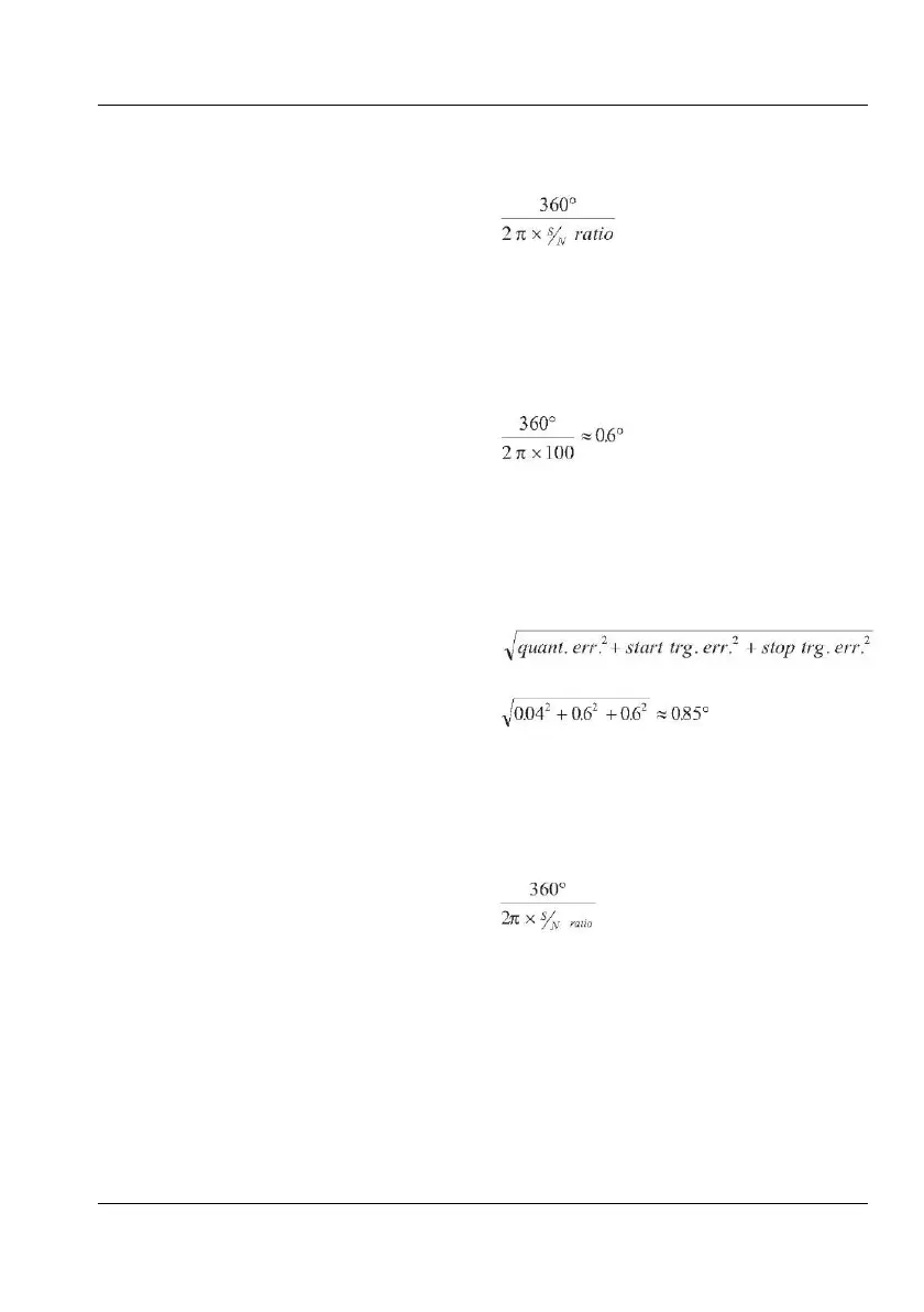
The trigger noise error consists of start and
stop trigger errors that should be added. For
sinusoidal input signals each error is:
Let's use the example above and add some
noise so that the S/N ratio will be 40 dB. This
corresponds to an amplitude ratio of 100
times (and power ratio of 10000 times). Then
the trigger noise will contribute to the random
error with:
The sum of random errors should not be
added linearly, but in an "RMS way", because
of their random nature. Let's do so for our
examples above.
Random error =
The total random errors are thus:
What about random errors caused by internal
amplifier noise? Internal noise contribution is
normally negligible. The phase error caused
by noise on the signal, whether internal or ex-
ternal, is:
For an input signal of 250 mV
rms
and the typi-
cal internal noise figure of 250 V
rms gives us
a S/N-ratio of a minimum of 60 dB (1000
times). This gives us a worst case error of
0.06°. Increasing the input signal to 1.5 V
rms
decreases the error to 0.01°.
Another way to decrease random errors is to
use the statistics features of the instrument
USER MANUAL ● CNT 9x Series ● Rev.22 February 2020