system control relays. These screens also identify the firmware versions on the controller. You can use the
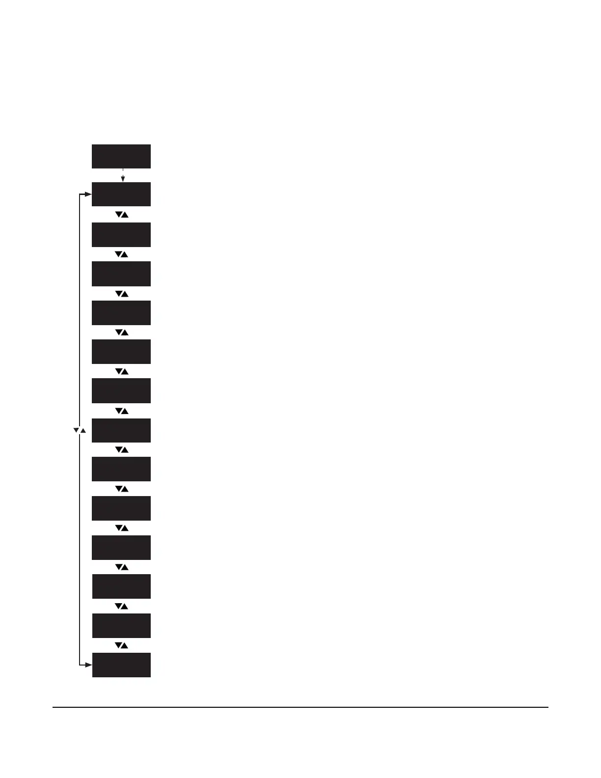
To view the SYSTEM STATUS screens, navigate to the SYSTEM STATUS start
screen and press SET.
The SN1: COOLING TEMP screen displays the temperature at the cooling control
sensor Sn1.
The SN2: DEFROST TERM TEMP screen displays the temperature at the defrost
termination sensor Sn2.
The NEXT DEFROST: SCHEDULED screen displays the start time of the next
defrost cycle.
The UI 4 screen displays the status of UI 4.
The UI 5 screen displays the status of UI 5.
The HVBIN: DEFROST TERM SWITCH screen displays the status of the thermal
defrost switch that is connected to the HVBIN terminals.
The COMPRESSOR: RELAY screen displays the status of the compressor relay
as open or closed.
The DEFROST: RELAY screen displays the status of the compressor relay as open
or closed.
The LO-SPD/AUX: RELAY screen displays the status of the lo-spd aux fan relay as
open or closed.
The HI-SPD: RELAY screen displays the status of the high-speed fan relay as
open or closed.
The ALARM: RELAY screen displays the status of the alarm relay as open or
closed.
The FW screen displays the main firmware version on the controller.
The FW UI screen displays the UI firmware version on the controller.

 Loading...


