4
A5xx Controller UI
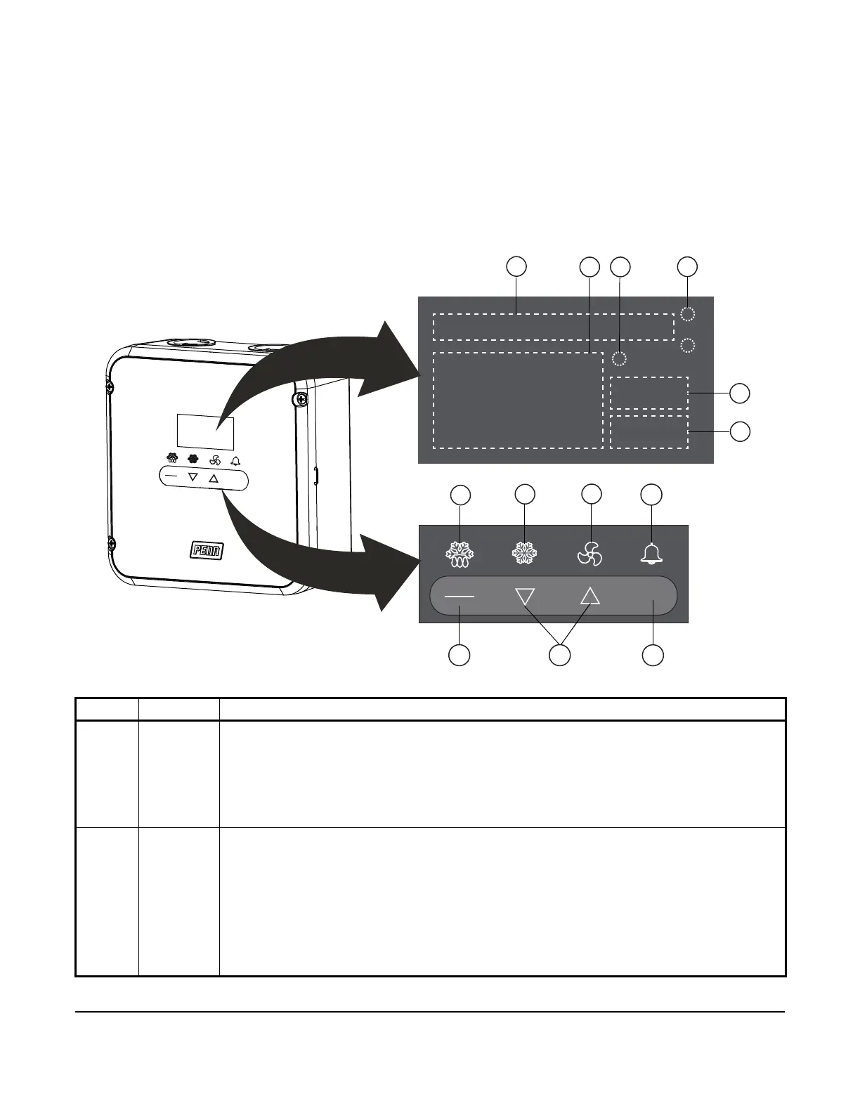
The A5xx Controller’s system status and setup information displays on an LCD UI with adjustable brightness. The
four status indicator icons show the defrost, cooling, evaporator fan, and alarm features and provide a visual
indication of the system status and alarms. The Defrost and Alarm icons also function as keys. You can use these
keys to initiate unscheduled defrost cycles and clear system alarms. You can also use the four touchpad keys to
navigate the system, see system information, change parameter settings, and respond to system alarms. The
following figure shows the controller’s UI, icons, and keys.
Figure 1: A5xx Controller UI with display fields, icons, and touchpad keys
Table 1: A5xx Controller UI with display fields, icons, and touchpad keys callout table (Part 1 of 2)
Callout Item Description, behavior, or user-action
1 Message
field
The message field shows messages with up to 8 characters that define the purpose of or value
displayed in the current screen. Messages with more than 8 characters automatically scroll across
the field. Message field messages include the following information:
• Displays the system name, the date, and the time during normal operation.
• Displays the setup parameter names as you navigate through the setup screens during setup.
• Displays drip-time, fan delay, and anti-short cycle delay countdowns during defrost duration.
The message field identifies the countdown and displays the minutes remaining.
2 Status
field
The status field displays the numerical values related to the status or setup parameter information
displayed in the message field. Status field values include the following information:
• Displays the temperature sensed at the main sensor (Sn1) during normal operation.
• Displays the current numerical value in the system status screens.
• Displays the flashing setup parameter values as you navigate through the setup screens with
editable values during setup.
• Displays four dashes during anti-short cycle delay, defrost duration, drip-time, and fan delay
countdowns. When you select or edit a numerical parameter value, the status field displays a
blinking value. When the current value blinks in the status field, press the DOWN or UP arrow
keys to select a different value. To save the value that displays, press SET.
1
3
5
8
9
10
11
13

 Loading...


