39
A5xx Controller screens
The following table provides information about the screens that you may encounter when you set up the A5xx
Controller for your refrigeration system. You can view the black screens in the controller’s UI. The gray screens
display only when relevant to the application requirements you select in the setup screens.
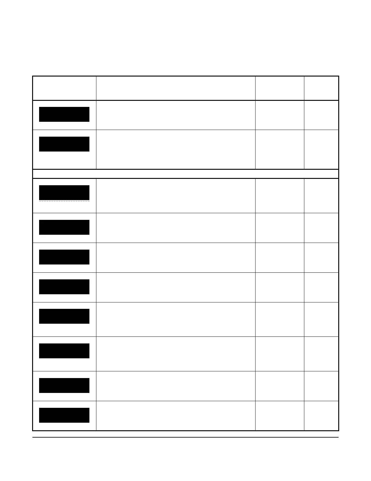
Table 15: A5xx Controller screens (Part 1 of 15)
Screen name in
message field
Parameter description, behavior, or user action Value range or
selection list
Default
value or
selection
When the A5xx Controller powers on, the WELCOME screen
displays and then automatically transitions to the HOME
screen.
n/a n/a
The HOME screen displays the system name, the date, and the
time in the scrolling message field. The temperature at Sn1
displays in the status field. Your selections for temperature units
and the setpoint value display in the information fields. To go to
the SYSTEM STATUS start screen and the other high-level
menu start screens, press MENU/ESC.
n/a n/a
System status screens
The SYSTEM STATUS screen is the top-level screen for
viewing the status of the refrigeration system. To move through
the SYSTEM STATUS screens, press the DOWN and UP arrow
keys. To go to the Sn1: COOLING TEMP screen press SET.
n/a n/a
This screen displays the temperature at the cooling control
sensor Sn1.
Current
temperature
value
n/a
This screen displays the temperature at the defrost termination
sensor Sn2.
Current
temperature
value
n/a
This screen displays the start time of the next defrost cycle. Real-time value n/a
This screen displays the following information about UI 4:
• The binary input displays as OP/EN (open) or CLO/SED
(closed) in the upper information field.
• The analog input displays as a 0 VDC to 10 VDC value in
the status field.
• OP/EN
• CLO/SED
• 0 VDC to 10
VDC
n/a
This screen displays the following information about UI 5:
• The binary input displays as OP/EN or CLO/SED in the
upper info field.
• The analog input displays as a 0 VDC to 10 VDC value in
the status field.
• OP/EN
• CLO/SED
• 0 VDC to 10
VDC
n/a
This screen displays the status of the user-supplied high-
voltage, binary input switch connected to the HV/BIN terminals.
• OP/EN
• CLO/SED
n/a
This screen displays the status of the compressor relay as open
or closed.
• OP/EN
• CLO/SED
n/a
SN2: DEFROST
TERM TEMP
25°
F
NEXT DEFROST:
SCHEDULED
12:00 AM
HVBIN: DEFROST
TERM SWITCH
OP
EN
 Loading...


