8
High-voltage terminal blocks and terminals
The following figure and table provide information about the high-voltage wiring terminal blocks and wiring terminal
labels.
Note: For detailed wiring guidelines and instructions, refer to the A5xx Series Wall Mount Refrigeration and
Defrost Controller Installation Instructions (part no. 24-7664-3310).
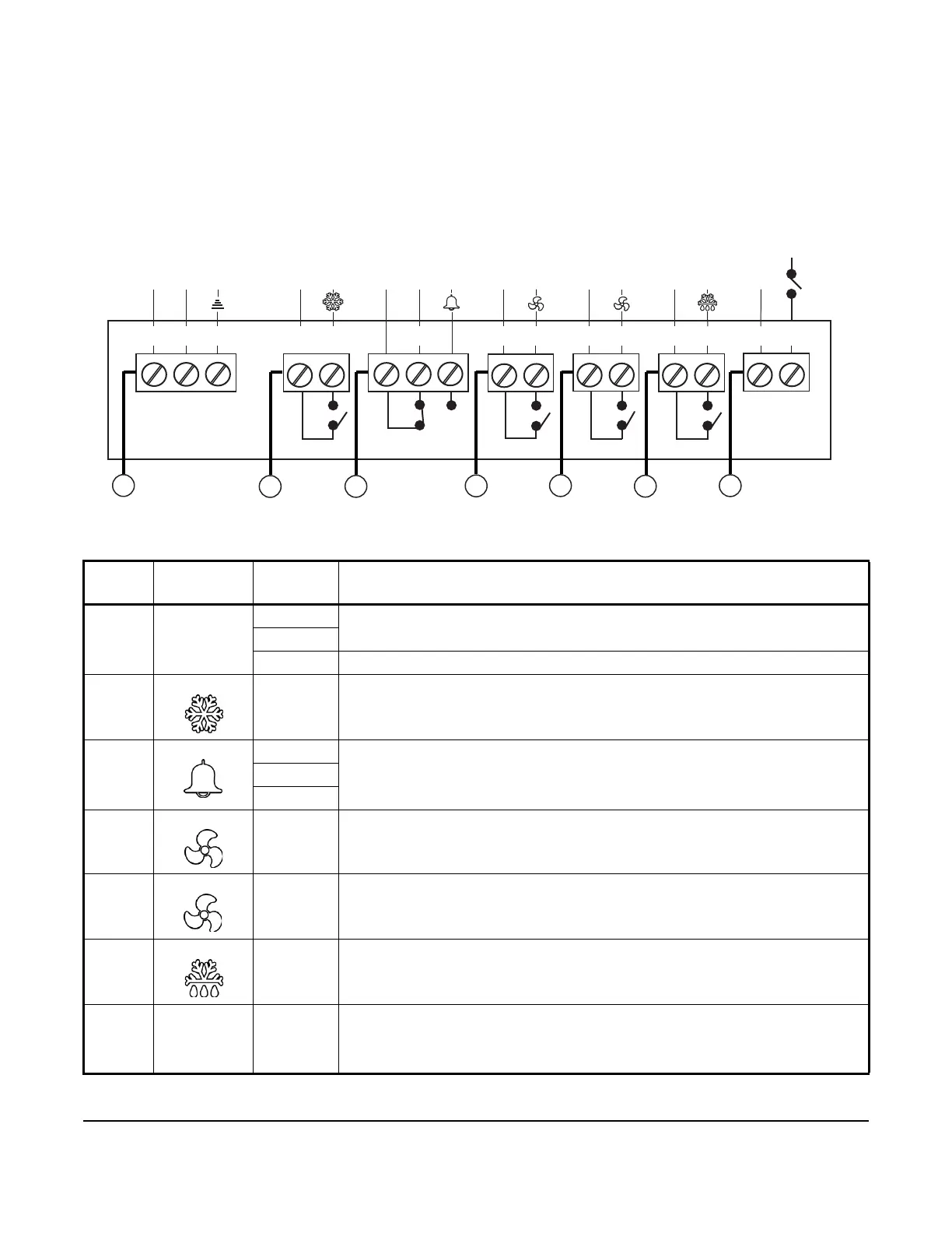
Figure 4: A5xx Controller high-voltage terminal block connections (internal to control)
Table 3: A5xx Controller high-voltage terminal blocks, terminals, and wire sizes
Callout Terminal
block label
Terminal
functions
Description, function, and requirements
1 90 VAC to
240 VAC
L1 Two terminals for supply power connection to the A5xx Controller. Requires 90 VAC
to 240 VAC; 15 VA (0.25 A maximum).
L2/N
GND Earth ground connection terminal.
2 Compressor Two terminals for line-voltage, single-pole, single-throw (SPST), dry-contact relay to
control the compressor or solenoid valve.
3 Alarm LC The common (LC), normally-open (LNO), and normally-closed (LNC) terminals for
line-voltage, single-pole, double-throw (SPDT), dry-contact relay to control the user-
supplied alarm devices.
LNC
LNO
4 Lo-spd aux The A5xx Controller includes two terminals for line-voltage, SPST, dry-contact relay
to control an auxiliary device such as a user-provided alarm device or the low-
speed on two-speed evaporator fans.
5 Hi-spd Two terminals for line-voltage, SPST, dry-contact relay to control single-speed
evaporator fans or the high-speed (hi-spd) on two-speed evaporator fans.
6 Defrost Two terminals for line-voltage, SPST, dry-contact relay to control resistive defrost
heater or bypass defrost solenoid.
7 HVBIN Two line-voltage binary input terminals for use with the line-voltage defrost
temperature termination switch. These terminals require an external power source
to provide 120 VAC to 240 VAC, 50/60 Hz activation power when the external, user-
supplied defrost termination switch closes.
GND
L1
L2/N
L1
(LC)
LNC
L2/N
(LNO)
L1
L2/N
L1
L2/N
L1
L2/N
L1
L2/N
L1
L2/N
90 VAC to 240 VAC COMPRESSOR ALARM LO-SPD AUX HI-SPD DEFROST HVBIN
2
6
7

 Loading...


