IC-KP-B17-AIDA1
Product Description
2014-02
13
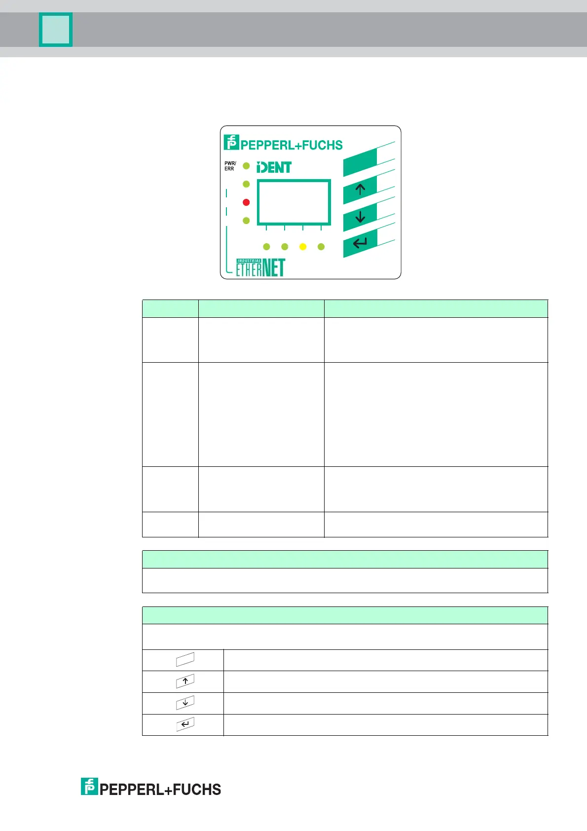
4.4 Displays and Controls
The following displays and controls are located on the control interface.
LEDs
Description Function Statu s descrip tion
CH1
CH2
CH3
CH4
Statu s display fo r the
read/write heads
LED illuminates green as soon as there is an active
command on the read/write head.
LED illuminates yellow for approx. 1 second as
soon as a command is executed successfully.
PWR/ERR Statu s display fo r
IDENTControl
LED illuminates green as soon as the
IDENTControl is connected to a power supply and
the interface is ready for operation.
LED illuminates red as soon as there is a hardware
error or a PROFINET name has been assigned and
no PROFINET connection has been established.
LED flashes green as soon as a signal has been
sent to the IDENTControl via the "Flashing"
PROFINET function or if there is an internal data
overflow.
Link1/Link2 Connection to the network
for channel 1/channel 2
LED is off until initial communication is made via
Ethernet.
LED illuminates green as soon as a connection to
the network is established.
Tra ffi c Network activity LED flashes green as soon as the IDENTControl
sends data.
Display
Two-line multifunction display with 12 characters per line for displaying different status and
operating information and four pictograms for displaying connected reading heads.
Push buttons
Push buttons are used for controlling the display and selecting commands when programming
the control interface.
Return to higher level
Up menu item
Down menu item
RETURN (confirm input)
Link1
Link2
Traffic
CH1 CH2 CH3 CH4
Control
IC-KP-B17-AIDA1
ESC
ESC