2014-02
110
IC-KP-B17-AIDA1
Appendix A
A response appears in the input field:
12.2 Example 2
Assembly objects 104d/154d (separated mode) are used in the example. The following
functions are activated:
■
Set tag type IPC03 on channel 1 and channel 2.
■
Write data to a IPC03 tag.
■
Read data from a IPC03 tag.
The following prerequisites must be fulfilled:
■
One type IPH-XX R/W head is connected to channel 1 and channel 2 on the
IDENTControl.
■
One type IPC03 data carrier is located in front of each R/W head.
■
The IP address of the IDENTControl is set to a free address ().
■
The device is connected to the network.
Setting the connection parameters
Configure the parameters on the PLC as follows:
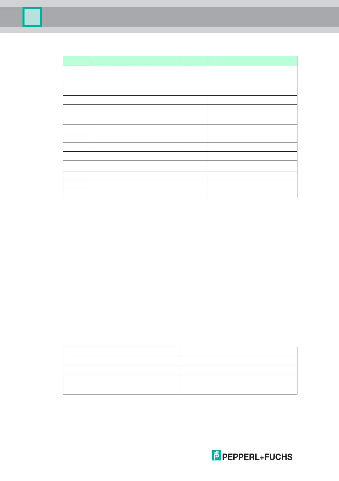
The selected input and output instances of the assembly object is divided as follows:
Byte no. Use Contents Description
Byte 0 Command code 01h Command SF (Single read read
only code)
Byte 1 Channel/Toggle bit 06h Channel = 3
To gg le b it = 0
Byte 2 Status 00h Command executed.
Byte 3 Reply counter 08h For every IDENT telegram, the
value on the reply counter
increases by 1.
Byte 4 ID code 00h ... FFh - <ID code>
Byte 5 ID code 00h ... FFh - <ID code>
Byte 6 ID code 00h ... FFh - <ID code>
Byte 7 ID code 00h ... FFh - <ID code>
Byte 8 ID code 00h ... FFh -
<ID code>
1
Byte 9 00h
Byte 10 00h
Byte 11 00h
1. only IPC02 and IPC11
Assembly instance Size (32 bits)
Input: 154 8
Output: 104 8
Configuration: 112
(this value is used for all input/output
instances)
0
(this value is used for all input/output
instances)