IC-KP-B17-AIDA1
Installation
2014-02
17
5.4 Device connection
Electrical connection using plug connectors makes installation simple.
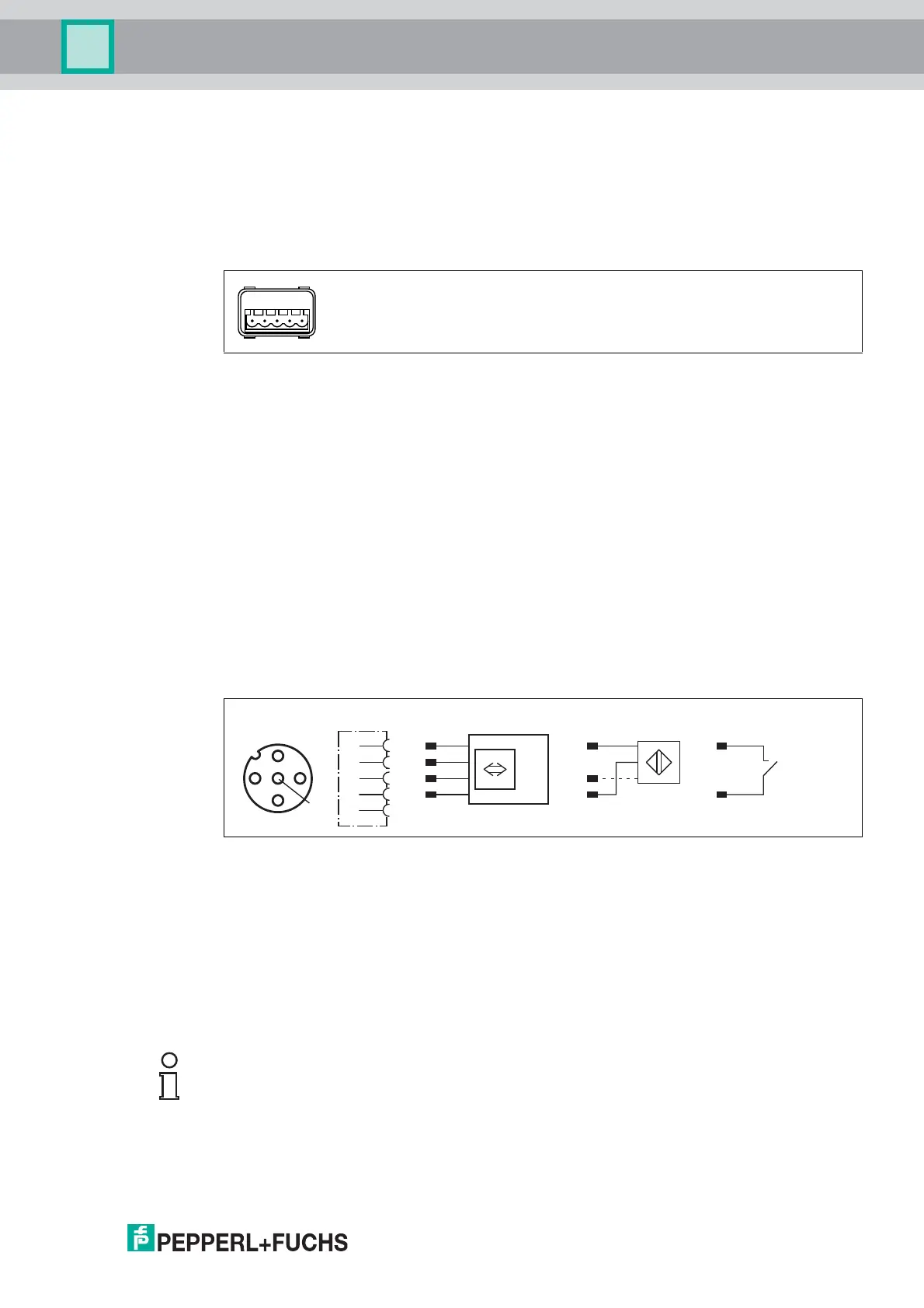
5.4.1 Power supply
Connect the power supply for the IDENTControl using a connector that conforms with AIDA. A
plug with the following pin assignment is located on the housing:
Compatible connecting cable see chapter 4.7.2.
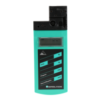
5.4.2 Read/Write Head and Trigger Sensors
A maximum of 4 read/write heads can be connected to the IDENTControl.
Instead of the read/write heads, a maximum of 2 trigger sensors can be connected to sockets 3
and 4. A trigger sensor can be assigned to only one read/write head. The trigger sensors must
be PNP.
Connect the read/write heads and trigger sensors to the sockets on the top of the enclosure
using M12 connectors.
For details of compatible read/write heads, see chapter 4.3.1 and of compatible connecting
cables, see chapter 4.7.1.
5.4.3 Cable length between control interface and R/W heads
The maximum cable length between the control interface and a connected R/W head is 1000
meters. If you wish to attain the maximum possible cable length, select a suitably large cable
cross-section. See chapter 4.7.1
5.4.4 Ground connection
Connect the IDENTControl interface to ground via a screw on the right under the housing.
1 + 24 V
2 GND
3 n.c.
4 n.c.
5 n.c.
trigger switch
trigger sensor
read/write head
signal
socket at housing
2
13
4
5
+
A
-
+
-
B
1
2
3
4
5
Note!
In order to guarantee safe grounding, mount the serrated washer between the crimp connector
and the housing.
Use a ground conductor lead with a cross-section of at least 4 mm
2
.