2014-02
32
IC-KP-B17-AIDA1
Commands
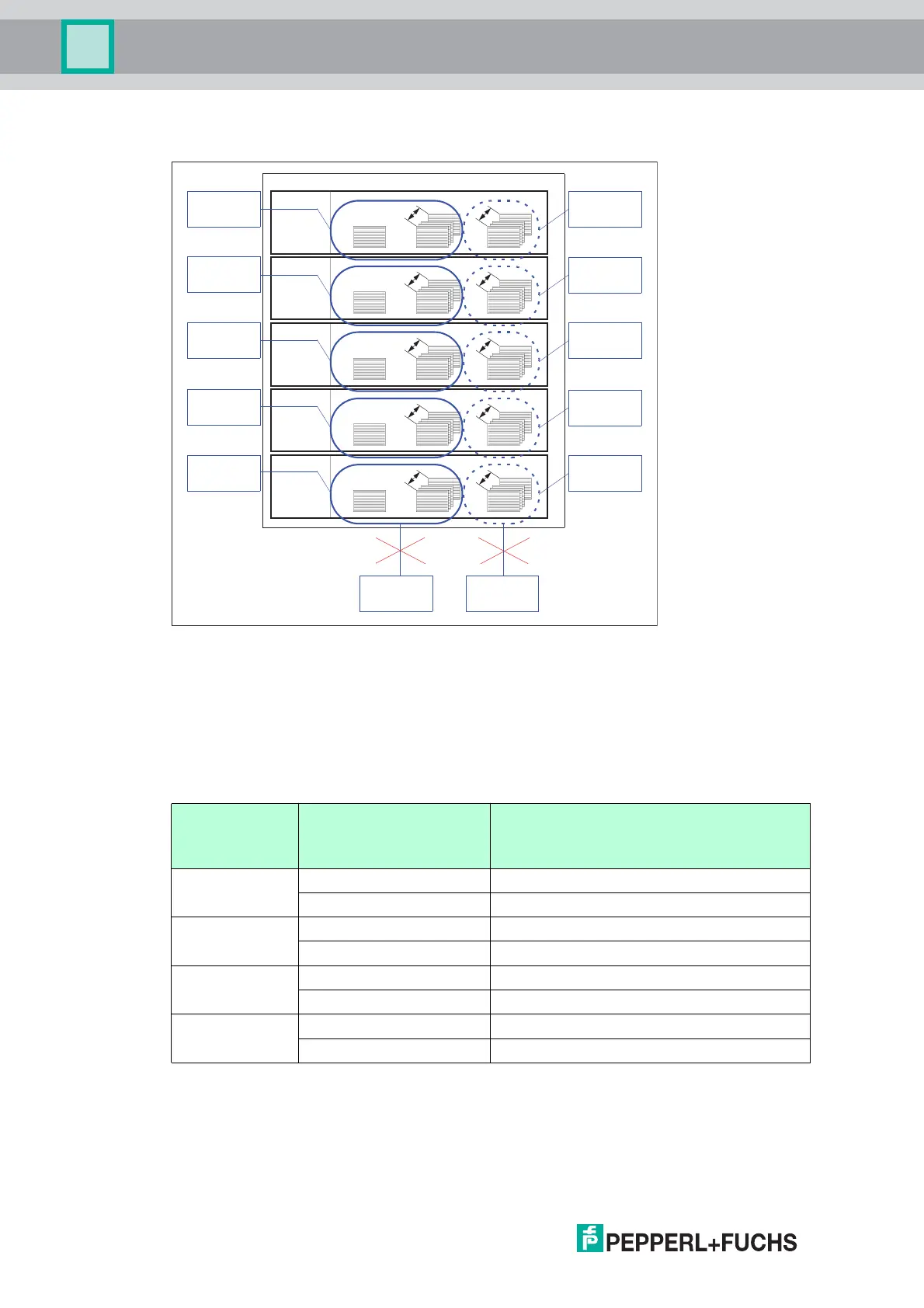
Example 2:
Description:
One controlling and one protocolling master are used for each channel. A protocolling master
can also access channels here.
Dual access to a register group within one channel is never permitted.
Group 1: Output register
Each area of this group is divided as follows:
K = 0, 1000, 2000, 3000, 4000
I = 3, 4, 5...
If the deletion bit is set, all data stored in the FIFO of the relevant channel (defined by K) is
deleted. The delete operation only starts if the status of the deletion bit changes from 0 to 1.
Address
(0-based,
decimal)
Byte number of the
identification telegram
Use
0 + K - Reserved
- Reserved/Deletion bit (LSB)
1 + K Byte 0 Telegram length, high byte [(N+1) div 256]
Byte 1 Telegram length, low byte [(N+1) mod 256]
2 + K Byte 2 Command code
Byte 3 Reserved/Toggle bit
I + K Byte N-1 Parameters
Byte N Parameters
Table 7.2 Output register
Channel 0
(IDENT Control)
Channel 1
Channel 2
Channel 3
Channel 4
Group 1 Group 2 Group 3
0
122
0
124
0
124
3
2
3
2
1000
1122
3
2
3
2
1000
1124
1000
1124
2000
2122
3
2
3
2
2000
2124
2000
2124
3000
3122
3
2
3
2
3000
3124
3000
3124
4000
4122
3
2
3
2
4000
4124
4000
4124
Controlling
Logging
Master 4
Master 4
Controlling
Logging
Master 3
Master 3
Controlling
Logging
Master 2
Master 2
Controlling
Logging
Master 1
Master 1
Controlling
Logging
Master 0
Master 0
Controlling
Logging
Master 5
Master 5