2014-02
38
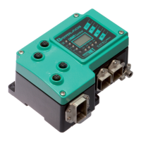
IC-KP-B17-AIDA1
Commands
read/write multiple registers (17h)
This MODBUS command combines the functionality of the read holding registerscommand
with the write multiple registerscommand. This command should always be used when data
is exchanged cyclically via a controller. The following should be noted:
If an identification command is initiated via this MODBUS command (for example, a read
command), the answer to this command is not included in the response associated with this
request. The data is only available after the time required to process the command has
elapsed.
If an identification command is initiated several times (e.g., if you wish to execute a read
command several times in succession), the first four bytes of the identification telegram must
be modified accordingly. The toggle bit can be used for this.
Process:
1. A request is issued. The following parameters must be known here:
Writing:
2002d High byte
Byte 2
Command code 19h enhanced read
command
Low byte
Byte 3
Word number/Channel/
To gg l e b i t
04h Word count = 0.
4 corresponds to
channel 2. Channel
number shifted 1 bit to
the left.
2003d High byte
Byte 4
Status 05h 05h = identification
read error (meaning of
the identification
statuses see chapter
10.1)
Low byte
Byte 5
Reply counter 02h Increases by 1 after
each additional
response.
2004d -
2011d
High byte Data 00h No data read because
no data carrier in front
of the read head.
Low byte Data 00h No data read because
no data carrier in front
of the read head.
Table 7.12 Response to the executed identification command enhanced read
Address
(0-based)
Register division
Byte number of the
identification
telegram
Use Contents Meaning
Note!
If a type IPC03 data carrier is held in front of the reading head, the data can be viewed if a read
holding registers command is executed repeatedly.
Start address (depending on channel) Channel 0 0d
Channel 1 1000d
Channel 2 2000d
Channel 3 3000d
Channel 4 4000d
Number of registers to be written: Maximum 121d
Table 7.13 Parameters required for a request